FUEL INJECTOR(for Port Injection) INSTALLATION

CAUTION / NOTICE / HINT
Note
This procedure includes the installation of small-head bolts. Refer to Small-Head Bolts of Basic Repair Hint to identify the small-head bolts.
PROCEDURE
-
INSTALL PORT FUEL INJECTOR ASSEMBLY
Tech Tips
Perform "Inspection After Repair" after replacing a port fuel injector assembly.
-
w/ Canistaer Pump Module:
-
w/o Canistaer Pump Module:
-
Apply a light coat of gasoline to new O-ring, and install each port fuel injector assembly.
Note
Check that there is no damage or foreign matter on the groove of the port fuel injector assembly when installing the O-ring to each port fuel injector assembly.
-
Attach the 2 claws and connect the No. 8 engine wire to the No. 1 fuel delivery pipe sub-assembly LH.
-
Connect the 3 connectors to the 3 port fuel injector assemblies.
-
Install the 3 port fuel injector assemblies to the No. 1 fuel delivery pipe sub-assembly LH.
Note
-
Check that the port fuel injector assembly installation holes of the No. 1 fuel delivery pipe sub-assembly LH are not damaged and are free of foreign matter.
-
Make sure that the O-ring is not damaged, twisted or moved out of place when installing the port fuel injector assembly.
-
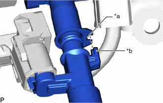
*a Groove *b Protrusion Align the protrusion of the port fuel injector assembly to the groove of the No. 1 fuel delivery pipe sub-assembly LH.
-
-
Attach the 2 claws and connect the No. 7 engine wire to the No. 1 fuel delivery pipe sub-assembly RH.
-
Connect the 3 connectors to the 3 port fuel injector assemblies.
-
Install the 3 port fuel injector assemblies to the No. 1 fuel delivery pipe sub-assembly RH.
Note
-
Check that the port fuel injector assembly installation holes of the No. 1 fuel delivery pipe sub-assembly RH are not damaged and are free of foreign matter.
-
Make sure that the O-ring is not damaged, twisted or moved out of place when installing the port fuel injector assembly.
-
*a Groove *b Protrusion Align the protrusion of the port fuel injector assembly to the groove of the No. 1 fuel delivery pipe sub-assembly RH.
-
-
-
INSTALL NO. 1 FUEL DELIVERY PIPE SUB-ASSEMBLY LH
-
Install 3 new injector vibration insulator to the cylinder head sub-assembly LH.
-
Install the No. 1 fuel delivery pipe spacers to the cylinder head sub-assembly LH.
-
Install the No. 1 fuel delivery pipe sub-assembly LH to the cylinder head sub-assembly LH with the 2 bolts.
- Torque:
- 21 N*m { 214 kgf*cm, 15 ft.*lbf }
Note
If a port fuel injector assembly is dropped or the tip of the port fuel injector assembly is struck, replace it with a new one.
-
Attach the clamp and connect the No. 8 engine wire to the wire harness clamp bracket.
-
Connect the connector to the No. 8 engine wire.
-
Connect the connector to the camshaft position sensor.
-
-
INSTALL NO. 2 FUEL PRESSURE SENSOR
-
INSTALL NO. 1 FUEL DELIVERY PIPE SUB-ASSEMBLY RH
-
Install 3 new injector vibration insulator to the cylinder head sub-assembly RH.
-
Install the No. 1 fuel delivery pipe spacers to the cylinder head sub-assembly RH.
-
Install the No. 1 fuel delivery pipe sub-assembly RH to the cylinder head sub-assembly RH with the 2 bolts.
- Torque:
- 21 N*m { 214 kgf*cm, 15 ft.*lbf }
Note
If a port fuel injector assembly is dropped or the tip of the port fuel injector assembly is struck, replace it with a new one.
-
Attach the clamp and connect the No. 7 engine wire to the wire harness clamp bracket.
-
Connect the connector to the No. 7 engine wire.
-
Connect the connector to the camshaft position sensor.
-
Connect the connector to the fuel pressure sensor.
-
-
INSTALL INTAKE MANIFOLD
-
Install 2 new gaskets to the lower intake manifold sub-assembly.
-
Install the intake manifold to the lower intake manifold sub-assembly with the 8 bolts.
- Torque:
- 24 N*m { 245 kgf*cm, 18 ft.*lbf }
-
-
INSTALL FUEL HOSE PROTECTOR
-
Install the fuel hose protector to the intake manifold with the 2 bolts.
- Torque:
- 21 N*m { 214 kgf*cm, 15 ft.*lbf }
-
Connect the 2 No. 2 turbo pressure sensors to the fuel hose protector.
-
Install the fuel hose bracket to the fuel hose protector with the bolt.
- Torque:
- 10 N*m { 102 kgf*cm, 7 ft.*lbf }
-
-
INSTALL FUEL TUBE SUB-ASSEMBLY
-
Attach the clamp and install the fuel tube sub-assembly to the fuel hose bracket.
-
Connect the fuel tube sub-assembly to the No. 1 fuel delivery pipe sub-assembly LH.
-
Connect the fuel tube sub-assembly to the No. 1 fuel delivery pipe sub-assembly RH.
-
-
INSTALL FUEL TUBE SUB-ASSEMBLY
-
Attach the clamp and install the fuel tube sub-assembly to the fuel hose bracket.
-
Connect the fuel tube sub-assembly to the fuel pump assembly.
-
-
CONNECT FUEL TUBE SUB-ASSEMBLY
-
Connect the fuel tube sub-assembly to the fuel tube sub-assembly.
-
-
INSTALL INTAKE AIR SURGE TANK ASSEMBLY WITH INTERCOOLER
-
INSTALL COWL TOP VENTILATOR LOUVER SUB-ASSEMBLY
-
CONNECT CABLE TO NEGATIVE BATTERY TERMINAL
Note
When disconnecting the cable, some systems need to be initialized after the cable is reconnected.
-
INSPECT FOR FUEL LEAK
-
PERFORM INITIALIZATION
-
Perform "Inspection After Repair" after replacing a port fuel injector assembly.
-
w/ Canistaer Pump Module:
-
w/o Canistaer Pump Module:
-
-