INTERCOOLER INSTALLATION
CAUTION / NOTICE / HINT
Note
This procedure includes the installation of small-head bolts. Refer to Small-Head Bolts of Basic Repair Hint to identify the small-head bolts.
PROCEDURE
-
INSTALL INTAKE AIR SURGE TANK ASSEMBLY WITH INTERCOOLER
-
Install a new gasket to the intake air surge tank assembly with intercooler.
Tech Tips
Check that the gasket is securely fitted into the groove on the installation area.
-
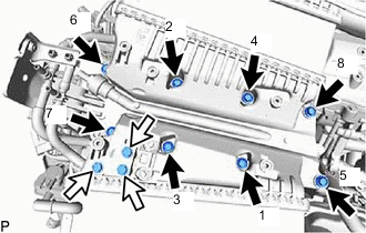

Intake Air Surge Tank Assembly with Intercooler Installation Bolt 
Do not Tighten the Non-removable Bolt. Install the intake air surge tank assembly with intercooler with the 8 bolts in the order shown in the illustration.
- Torque:
- 21 N*m { 214 kgf*cm, 15 ft.*lbf }
Note
Do not tighten the non-removable bolt.
-
Connect the No. 1 PCV hose to the intake air surge tank assembly with intercooler, and slide the clip to secure the hose.
-
Install the 2 bolts.
- Torque:
- 10 N*m { 102 kgf*cm, 7 ft.*lbf }
-
-
INSTALL NO. 2 INTERCOOLER SUPPORT BRACKET
-
Install the No. 2 intercooler support bracket with the bolt and nut to the intake air surge tank assembly with intercooler and cylinder head cover sub-assembly LH.
- Torque:
- 10 N*m { 102 kgf*cm, 7 ft.*lbf }
-
-
INSTALL INTERCOOLER SUPPORT BRACKET
-
Install the intercooler support bracket with the bolt and nut to the intake air surge tank assembly with intercooler and cylinder head cover sub-assembly RH.
- Torque:
- 10 N*m { 102 kgf*cm, 7 ft.*lbf }
-
-
INSTALL NO. 2 SURGE TANK STAY
-
Install the No. 2 surge tank stay with the 2 bolts to the intake air surge tank assembly with intercooler and No. 2 timing chain cover assembly.
- Torque:
- 10 N*m { 102 kgf*cm, 7 ft.*lbf }
-
-
INSTALL NO. 1 SURGE TANK STAY
-
Install the No. 1 surge tank stay with the 2 bolts to the intake air surge tank assembly with intercooler and No. 2 timing chain cover assembly.
- Torque:
- 10 N*m { 102 kgf*cm, 7 ft.*lbf }
-
-
INSTALL E.F.I. VACUUM SENSOR ASSEMBLY
-
INSTALL NO. 3 TURBO PRESSURE SENSOR
-
INSTALL NO. 8 FUEL VAPOR FEED HOSE
-
Install the No. 8 fuel vapor feed hose to the intake air surge tank assembly with intercooler and fuel vapor feed pipe sub-assembly, and slide the clips to secure the hose.
-
-
INSTALL NO. 9 FUEL VAPOR FEED HOSE
-
Install the No. 9 fuel vapor feed hose to the intake air surge tank assembly with intercooler and fuel vapor feed pipe sub-assembly, and slide the clips to secure the hose.
-
-
INSTALL NO. 10 ENGINE WIRE
-
Connect the connectors, attach the clamps to connect the No. 10 engine wire from the intake air surge tank assembly with intercooler.
-
-
INSTALL NO. 9 ENGINE WIRE
-
Connect the connectors, attach the clamps to connect the No. 9 engine wire from the intake air surge tank assembly with intercooler.
-
-
INSTALL SURGE TANK COVER
-
Install the surge tank cover to the intake air surge tank assembly with intercooler.
-
-
INSTALL NO. 1 WATER BY-PASS TUBE
Note
Do not bend the No. 1 water by-pass tube when removing it.
-
Temporarily install the No. 1 water by-pass tube with the 6 bolts to the intake air surge tank assembly with intercooler.
-
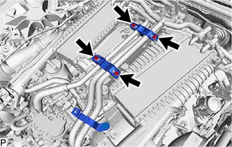
Tighten the 4 bolts.
- Torque:
- 10 N*m { 102 kgf*cm, 7 ft.*lbf }
-
Tighten the bolt.
- Torque:
- 10 N*m { 102 kgf*cm, 7 ft.*lbf }
-
Tighten the bolt.
- Torque:
- 10 N*m { 102 kgf*cm, 7 ft.*lbf }
-
for Bank 1:
-

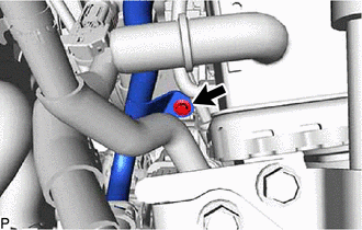
Connect the No. 1 Water By-pass Pipe 
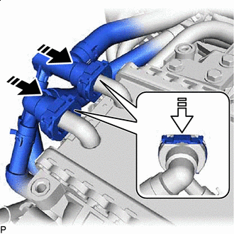
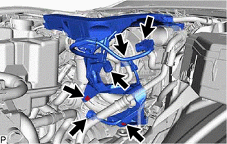
Insert the Retainer in the Direction of the Arrow Shown in the Illustration. Connect the No. 1 water by-pass pipe to the intake air surge tank assembly with intercooler and slide the retainer to secure it as shown in the illustration.
Note
-
Push in the retainer until a click sound is heard.
-
Pull on the No. 1 water by-pass pipe to confirm that the hose is securely connected.
-
If there is foreign matter on the union or the O-ring, clean it with water and finger scouring.
-
-
-
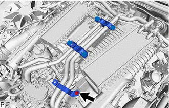
for Bank 2:
-
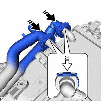
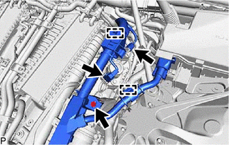
Connect the No. 1 Water By-pass Pipe Insert the Retainer in the Direction of the Arrow Shown in the Illustration. Connect the No. 1 water by-pass pipe to the intake air surge tank assembly with intercooler and slide the retainer to secure it as shown in the illustration.
Note
-
Push in the retainer until a click sound is heard.
-
Pull on the No. 1 water by-pass pipe to confirm that the hose is securely connected.
-
If there is foreign matter on the union or the O-ring, clean it with water and finger scouring.
-
-
-
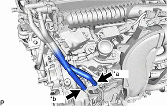
*a Paint Mark (yellow) *b Paint Mark (white) Connect the No. 1 turbo water hose and No. 2 turbo water hose to the No. 1 turbo water pipe sub-assembly, and slide the clips to secure the hose.
Note
Be sure to correctly connect the No. 1 turbo water hose and No. 2 turbo water hose. Incorrect installation may damage the turbocharger sub-assembly.
Tech Tips
Make sure the paint mark on the pipe side and the paint mark on the hose side are the same color.
-
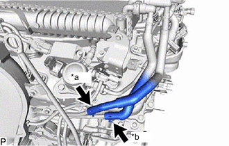
*a Paint Mark (yellow) *b Paint Mark (white) Connect the No. 3 turbo water hose and No. 4 turbo water hose to the No. 2 turbo water pipe sub-assembly, and slide the clips to secure the hose.
Note
Be sure to correctly connect the No. 3 turbo water hose and No. 4 turbo water hose. Incorrect installation may damage the turbocharger sub-assembly.
Tech Tips
Make sure the paint mark on the pipe side and the paint mark on the hose side are the same color.
-
Connect the No. 1 water by-pass hose to the No. 1 water by-pass tube, and slide the clip to secure the hose.
-
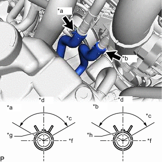
*a Intercooler Outlet Pipe *b Intercooler Inlet Pipe *c Clip Installation Range 120° *d Front Side *f Vehicle Left Side *g Paint Mark (blue) *h Paint Mark (yellow) Connect the intercooler cooling water inlet hose and intercooler cooling water outlet hose, and slide the clips to secure the hose to the No. 1 water by-pass tube.
Note
Make sure the hose clips and paint marks is oriented as shown in the illustration.
-
-
CONNECT OUTLET HEATER WATER HOSE
-
CONNECT INLET HEATER WATER HOSE
-
CONNECT ENGINE WIRE HARNESS
-
for Bank 1:
-
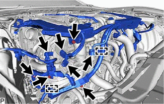
Connect the connectors and attach the clamps to connect the engine wire harness.
-
Install the 4 bolts.
- Torque:
- 10 N*m { 102 kgf*cm, 7 ft.*lbf }
-
-
Engine Front Side:
-
Connect the connectors and attach the clamps to connect the engine wire harness.
-
Install the 2 bolts.
- Torque:
- 10 N*m { 102 kgf*cm, 7 ft.*lbf }
-
Connect the connectors and attach the clamps to connect the engine wire harness.
-
Install the bolt.
- Torque:
- 10 N*m { 102 kgf*cm, 7 ft.*lbf }
-
-
for Bank 2:
-
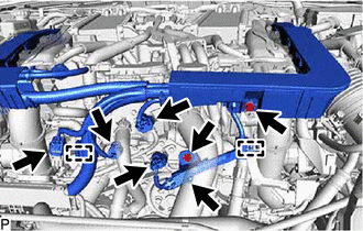
Connect the connectors to connect the engine wire harness.
-
Install the 2 bolts.
- Torque:
- 10 N*m { 102 kgf*cm, 7 ft.*lbf }
-
Connect the connectors and attach the clamps to connect the engine wire harness.
-
Install the bolt.
- Torque:
- 10 N*m { 102 kgf*cm, 7 ft.*lbf }
-
-
-
INSTALL NO. 1 VACUUM SWITCHING VALVE ASSEMBLY
-
INSTALL V-BANK COVER BRACKET
-
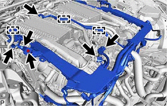
Install the No. 1 V-bank cover bracket and No. 2 V-bank cover bracket with the 4 bolts to the intake air surge tank assembly with intercooler.
- Torque:
- 10 N*m { 102 kgf*cm, 7 ft.*lbf }
-
-
INSTALL FUEL VAPOR FEED PIPE
-
Install the fuel vapor feed pipe with the 2 bolts to the intake air surge tank assembly with intercooler.
- Torque:
- 10 N*m { 102 kgf*cm, 7 ft.*lbf }
-
-
INSTALL THROTTLE BODY WITH MOTOR ASSEMBLY
-
ADD COOLANT (for Intercooler)
-
INSPECT FOR COOLANT LEAK (for Intercooler)