INTAKE MANIFOLD INSTALLATION
CAUTION / NOTICE / HINT
Note
This procedure includes the installation of small-head bolts. Refer to Small-Head Bolts of Basic Repair Hint to identify the small-head bolts.
PROCEDURE
-
INSTALL LOWER INTAKE MANIFOLD SUB-ASSEMBLY
-
for Bank 2:
-
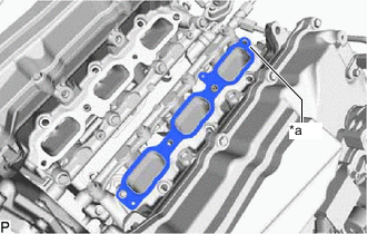
*a Paint Mark Set a new No. 1 intake manifold to head gasket on cylinder head as shown in the illustration.
-
Install the lower intake manifold sub-assembly with the 4 bolts.
- Torque:
- 28 N*m { 286 kgf*cm, 21 ft.*lbf }
-
-
for Bank 1:
-
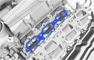
*a Paint Mark Set a new No. 1 intake manifold to head gasket on cylinder head as shown in the illustration.
-
Install the lower intake manifold sub-assembly with the 4 bolts.
- Torque:
- 28 N*m { 286 kgf*cm, 21 ft.*lbf }
-
-
-
INSTALL FUEL VAPOR FEED PIPE SUB-ASSEMBLY
-
Install the fuel vapor feed pipe sub-assembly to the lower intake manifold sub-assembly with the 2 bolts.
- Torque:
- 12 N*m { 122 kgf*cm, 9 ft.*lbf }
-
-
INSTALL NO. 2 MANIFOLD STAY
-
Install the No. 2 manifold stay to the lower intake manifold sub-assembly with the 4 bolts.
- Torque:
- 24 N*m { 245 kgf*cm, 18 ft.*lbf }
-
-
INSTALL NO. 1 FUEL DELIVERY PIPE SUB-ASSEMBLY LH
-
INSTALL NO. 1 FUEL DELIVERY PIPE SUB-ASSEMBLY RH
-
INSTALL INTAKE MANIFOLD
-
INSTALL FUEL HOSE PROTECTOR
-
INSTALL FUEL TUBE SUB-ASSEMBLY
-
INSTALL FUEL TUBE SUB-ASSEMBLY
-
CONNECT FUEL TUBE SUB-ASSEMBLY
-
INSTALL INTAKE AIR SURGE TANK ASSEMBLY WITH INTERCOOLER
-
INSTALL COWL TOP VENTILATOR LOUVER SUB-ASSEMBLY
-
INSPECT FOR FUEL LEAK