FRONT DOOR REMOVAL

Tech Tips
-
Use the same procedure for the RH and LH sides.
-
The procedure listed below is for the LH side.
-
PRECAUTION
Note
After turning the ignition switch off, waiting time may be required before disconnecting the cable from the battery terminal. Therefore, make sure to read the disconnecting the cable from the battery terminal notice before proceeding with work Click here.
-
DISCONNECT CABLE FROM NEGATIVE BATTERY TERMINAL
Note
When disconnecting the cable some systems need to be initialized after the cable is reconnected Click here.
-
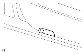
REMOVE FRONT DOOR INSIDE HANDLE BEZEL LH
-
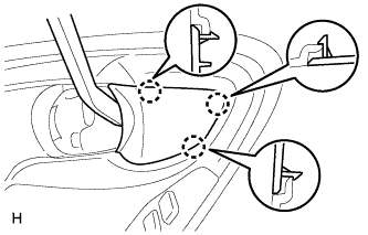
Using moulding remover A, detach the 3 claws and remove the inside handle bezel.
-
-
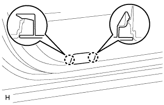
REMOVE FRONT DOOR TRIM MOULDING LH
-
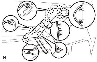
Using moulding remover A, detach the 8 claws and remove the front door trim moulding.
-
-
REMOVE POWER WINDOW REGULATOR MASTER SWITCH ASSEMBLY WITH FRONT DOOR ARMREST BASE PANEL (for Driver Side)
-
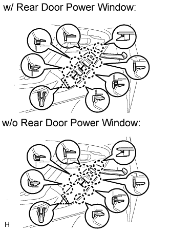
Using moulding remover A, detach the clip and 7 claws and remove the power window regulator master switch assembly with front door armrest base panel.
-
Disconnect the connector.
-
-
REMOVE POWER WINDOW REGULATOR SWITCH ASSEMBLY WITH FRONT DOOR ARMREST BASE PANEL (for Front Passenger Side)
Tech Tips
Use the same procedure described for the driver side.
-
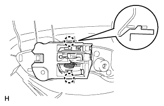
REMOVE POWER WINDOW REGULATOR MASTER SWITCH ASSEMBLY (for Driver Side)
-
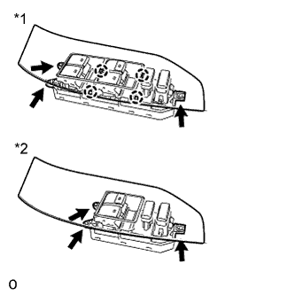
Text in Illustration *1 w/ Rear Door Power Window *2 w/o Rear Door Power Window w/ Rear Door Power Window:
-
Remove the 3 screws.
-
Using moulding remover A, detach the 4 claws and remove the master switch assembly.
-
-
w/o Rear Door Power Window:
-
Remove the 3 screws and master switch assembly.
-
-
-
REMOVE POWER WINDOW REGULATOR SWITCH ASSEMBLY (for Front Passenger Side)
-
Detach the 2 claws and remove the regulator switch.
-
-
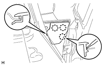
REMOVE FRONT DOOR TRIM BOARD SUB-ASSEMBLY LH
-
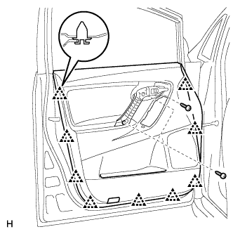
Remove the 3 screws.
-
Remove the 9 clips.
-
w/ Courtesy Light:
-
Disconnect the courtesy light connector.
-
-
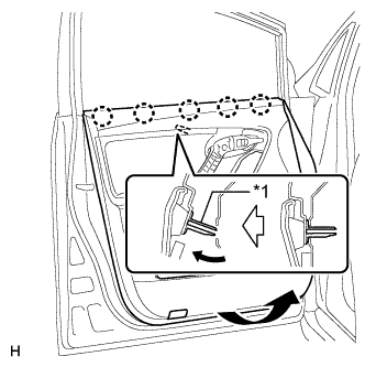
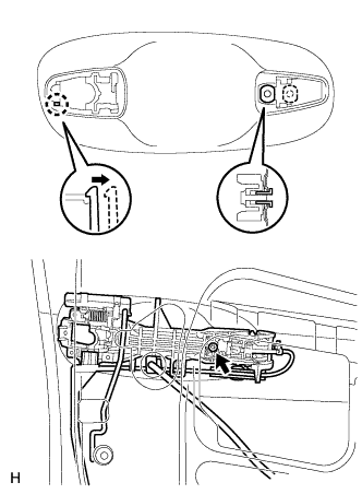
Text in Illustration *1 Reference Boss Pull out the rear door trim board in the direction indicated by the arrow.
-
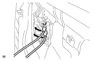
Disconnect the 2 cables from the inside handle.
-
-
REMOVE COURTESY LIGHT ASSEMBLY (w/ Courtesy Light)
-
Detach the claw.
-
Disconnect the connector and remove the light.
-
Remove the bulb.
-
-
REMOVE FRONT DOOR LOWER TRIM COVER (w/o Courtesy Light)
-
Detach the 2 claws and remove the front door lower trim cover.
-
-
REMOVE FRONT DOOR INSIDE HANDLE SUB-ASSEMBLY LH
-
Detach the 2 claws and remove the inside handle sub-assembly from the door trim board.
-
-
REMOVE FRONT DOOR INNER GLASS WEATHERSTRIP LH
-
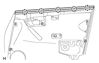
Detach the 5 claws and remove the weatherstrip.
-
-
REMOVE OUTER MIRROR INSTALL HOLE COVER LH
-
Using moulding remover D, detach the 3 claws and remove the outer mirror install hole cover.
-
-
REMOVE FRONT DOOR SERVICE HOLE COVER LH
-
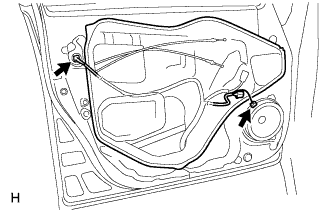
Disconnect the 2 connectors and remove the service hole cover.
Tech Tips
Remove the remaining tape on the door.
-
-
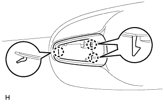
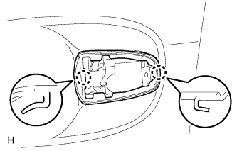
REMOVE OUTER REAR VIEW MIRROR ASSEMBLY LH
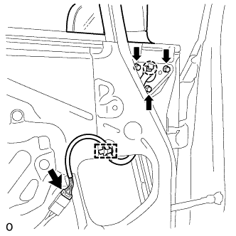
-
Disconnect the connector.
-
Detach the clamp.
-
Remove the 3 bolts, detach the claw and remove the outer rear view mirror assembly LH.
-
-
REMOVE FRONT NO. 1 SPEAKER ASSEMBLY
Note
Do not touch the cone part of the speaker.
-
Disconnect the speaker connector.
-
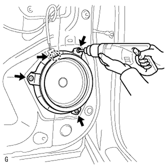
Using a drill bit with a diameter of less than 4 mm (0.157 in.), drill out the 3 rivet heads.
CAUTION:
Be careful as the cut rivet will be very hot.
Note
Do not drill the rivet at an angle as this will cause damage to the drill and drill hole. Line up the drill and rivet, and carefully drill out the rivet head.
-
Continue drilling and push out the remaining rivet fragments.
-
Using a vacuum cleaner, remove the rivet fragments and shavings from the inside of the door.
-
Detach the claw and remove the speaker.
-
-
REMOVE FRONT DOOR GLASS SUB-ASSEMBLY LH
-
for Driver Side:
Temporarily install the master switch assembly.
-
for Front Passenger Side:
Temporarily install the regulator switch assembly.
-
Connect the cable to the negative (-) battery terminal.
-
Move the door glass until the bolts appear in the service holes.
-
Disconnect the cable from the negative (-) battery terminal.
Note
When disconnecting the cable some systems need to be initialized after the cable is reconnected Click here.
-
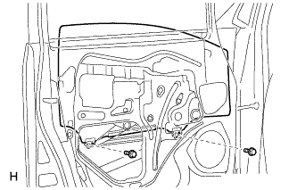
Remove the 2 bolts.
Note
Be careful when removing the bolts as the glass may fall and become damaged.
-
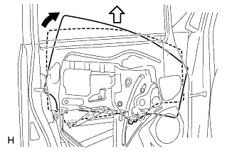
Remove the door glass in the direction indicated by the arrows in the illustration.
Tech Tips
Remove the glass upward.
Note
Be careful not to damage the glass.
-
for Driver Side:
Remove the master switch assembly.
-
for Front Passenger Side:
Remove the regulator switch assembly.
-
-
REMOVE FRONT DOOR GLASS RUN LH
-
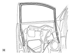
Remove the front door glass run.
-
-
REMOVE DOOR FRAME GARNISH LH
-
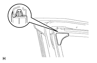
Detach the clip and remove the door frame garnish.
-
-
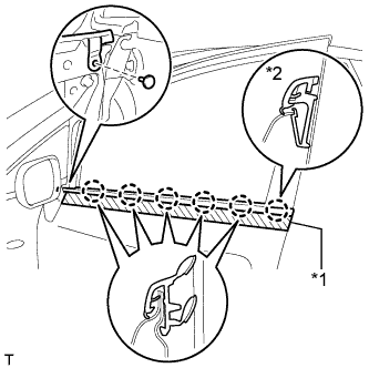
REMOVE FRONT DOOR BELT MOULDING ASSEMBLY LH
-
Put protective tape around the front door belt moulding assembly.
-
Remove the clip.
-
Detach the 6 claws and remove the front bumper moulding assembly.
Tech Tips
If the claw labeled A is damaged, replace the front door belt moulding with a new front door belt moulding.
Text in Illustration *1 Protective Tape *2 Claw A
-
-
REMOVE FRONT DOOR WINDOW REGULATOR ASSEMBLY LH
-
Disconnect the connector from the front door window regulator assembly.
-
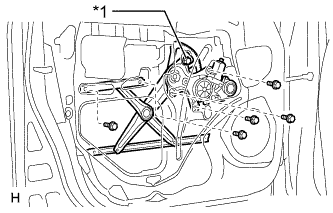
Text in Illustration *1 Temporary Bolt Loosen the temporary bolt.
Note
Do not remove the temporary bolt. If the temporary bolt is removed, the front door window regulator may fall and become damaged.
-
Remove the 5 bolts.
-
Remove the front door window regulator assembly.
-
Remove the temporary bolt from the front door window regulator assembly.
-
-
REMOVE FRONT DOOR REAR LOWER FRAME SUB-ASSEMBLY LH
-
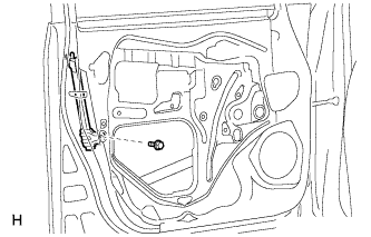
Remove the bolt and rear lower frame.
-
-
REMOVE FRONT DOOR OUTSIDE HANDLE COVER LH (for Driver Side)
-
Remove the hole plug.
-
Using a T30 "TORX" wrench, loosen the screw and remove the cover with the door lock key cylinder installed.
-
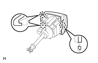
Using a screwdriver, disengage the 3 claws and remove the front door outside handle cover from the cylinder.
-
-
REMOVE FRONT DOOR OUTSIDE HANDLE COVER RH (for Front Passenger Side)
-
Remove the hole plug.
-
Using a T30 "TORX" wrench, loosen the screw and remove the front door outside handle cover.
-
-
REMOVE FRONT DOOR OUTSIDE HANDLE ASSEMBLY LH
-
w/ Entry and Start System:
-
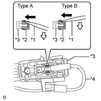
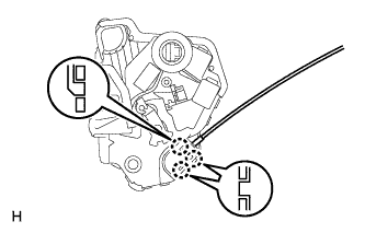
Text in Illustration *1 Screwdriver *2 Connector Cover *3 Front Door Outside Handle Assembly *4 Front Door Wire LH Disconnect the 2 claws of the connector cover as shown in the illustration.
-
Text in Illustration *1 Screwdriver *2 Front Door Wire LH Push the claw of the connector and disconnect the front door wire as shown in the illustration.
-
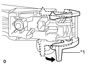
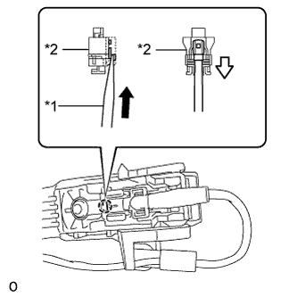
Text in Illustration *1 Holder Detach the holder as shown in the illustration.
-
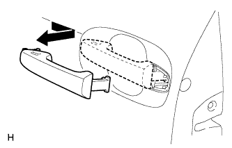
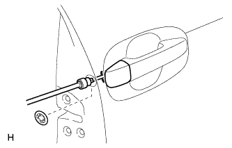
Remove the handle by sliding and pulling it in the direction indicated by the arrow in the illustration.
-
-
w/o Entry and Start System:
-
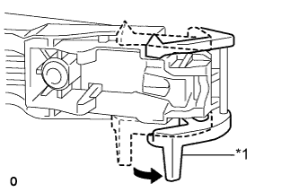
Text in Illustration *1 Holder Detach the holder as shown in the illustration.
-
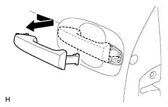
Remove the handle by sliding and pulling it in the direction indicated by the arrow in the illustration.
-
-
-
REMOVE FRONT DOOR FRONT OUTSIDE HANDLE PAD
-
Detach the 3 claws and remove the pad.
-
-
REMOVE FRONT DOOR REAR OUTSIDE HANDLE PAD
-
Detach the 2 claws and remove the pad.
-
-
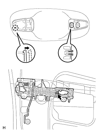
REMOVE FRONT DOOR LOCK ASSEMBLY LH
-
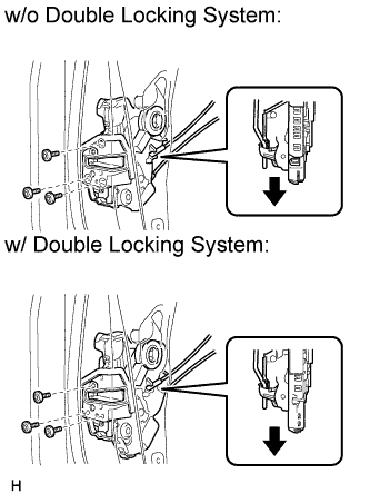
Using a T30 "TORX" wrench, remove the 3 screws.
-
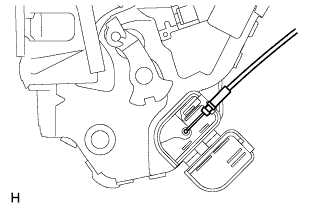
Slide the front door lock assembly downward, pull out the front door lock open rod from the outside handle frame, and remove the front door lock assembly and cables as a unit.
-
Remove the front door lock open rod from the front door lock assembly.
-
Remove the door lock wiring harness seal from the front door lock assembly.
-
-
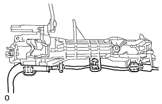
REMOVE FRONT DOOR LOCK REMOTE CONTROL CABLE ASSEMBLY LH
-
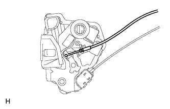
Remove the front door lock remote control cable assembly.
-
-
REMOVE FRONT DOOR INSIDE LOCKING CABLE ASSEMBLY LH
-
Using a screwdriver, detach the 3 claws.
Tech Tips
Tape the screwdriver tip before use.
-
Remove the front door inside locking cable assembly.
-
-
REMOVE FRONT DOOR OUTSIDE HANDLE FRAME SUB-ASSEMBLY LH
-
w/ Entry and Start System:
-
Detach the 3 clamps.
-
Using a T30 "TORX" wrench, loosen the screw.
-
Slide the outside handle frame and door wire to remove the outside handle frame.
Tech Tips
Remove the outside handle frame through the service hole.
-
Pull the front door outside handle frame sub-assembly together with the front door wire away from the vehicle.
-
Detach the 2 clamps and 2 claws and remove the front door outside handle frame from the front door wire.
-
-
w/o Entry and Start System:
-
Using a T30 "TORX" wrench, loosen the screw.
-
Slide the outside handle frame to remove it.
Tech Tips
Remove the outside handle frame through the service hole.
-
-
-
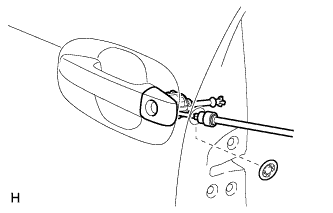
REMOVE FRONT DOOR LOCK OPEN ROD LH
-
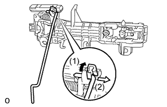
Remove the front door lock open rod as shown in the illustration.
-
-
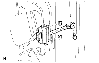
REMOVE FRONT DOOR CHECK ASSEMBLY LH
-
Remove the bolt, 2 nuts and door check.
Tech Tips
Remove the door check through the service hole.
Note
Be careful when removing the bolt and nuts as the door check may fall and become damaged.
-
-
REMOVE FRONT DOOR WEATHERSTRIP LH
-
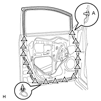
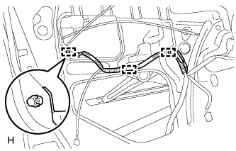
Using a clip remover, remove the clip labeled A.
-
Using a clip remover, detach the 14 clips and remove the weatherstrip.
Tech Tips
If clips are damaged during removal, replace them.
-
-
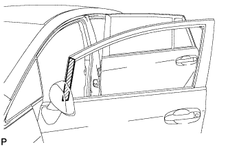
REMOVE NO. 1 BLACK OUT TAPE LH
-
Heat the vehicle body surface and black out tape using a heat light.
-
Pull back an edge of the black out tape and pull it parallel to the vehicle body to remove it.
-
-
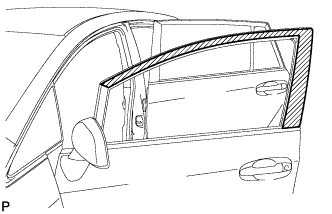
REMOVE NO. 2 BLACK OUT TAPE LH
-
Heat the vehicle body surface and black out tape using a heat light.
-
Pull back an edge of the black out tape and pull it parallel to the vehicle body to remove it.
-