LOWER INSTRUMENT PANEL INSTALLATION

Tech Tips
-
Use the same procedure for RHD and LHD vehicles.
-
The procedure listed below is for LHD vehicles.
-
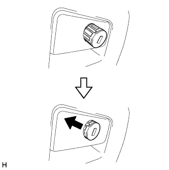
INSTALL GLOVE COMPARTMENT DOOR LOCK CYLINDER ASSEMBLY (for RHD)
-
Insert the end of the glove compartment door lock cylinder as shown in the illustration, hold down the stopper and install the glove compartment door lock cylinder.
-
-
INSTALL GLOVE COMPARTMENT DOOR STOPPER SUB-ASSEMBLY
-
Attach the claw to install the glove compartment door stopper.
-
-
INSTALL LOWER INSTRUMENT PANEL SUB-ASSEMBLY
-
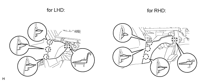
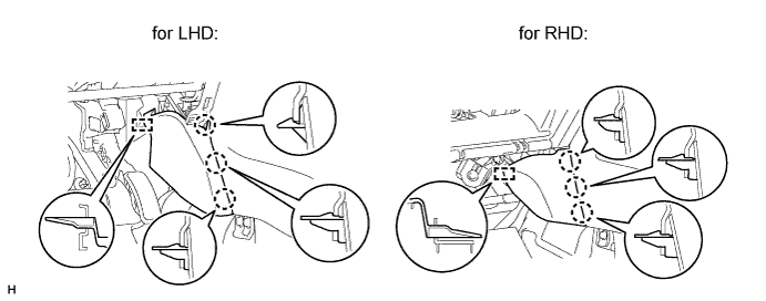
for LHD:
-
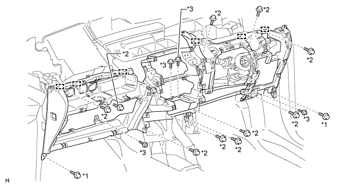
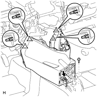
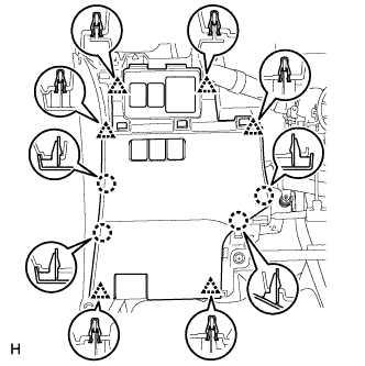
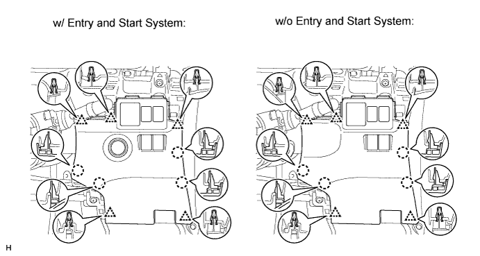
Attach the 6 guides to install the lower instrument panel.
-
Install the 4 screws <D> and 2 bolts <B>.
-
Install the 11 bolts <C>.
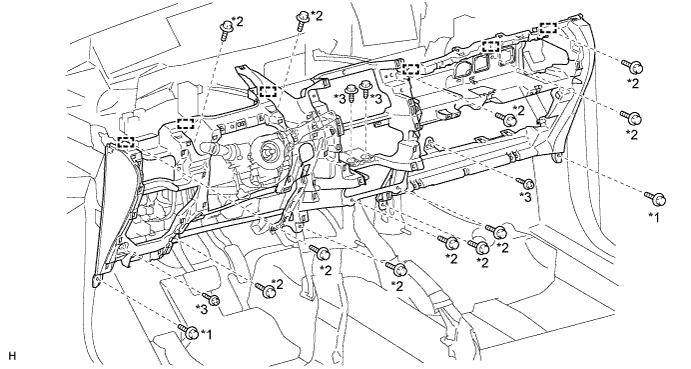
Text in Illustration *1 Bolt <B> *2 Bolt <C> *3 Screw <D> - - -
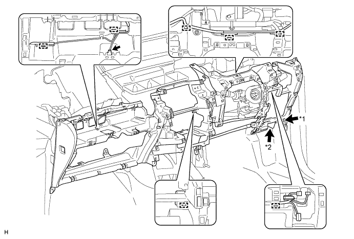
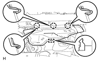
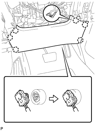
Connect the connectors and clamps.
-
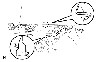
Connect the hood lock control cable and DLC3.
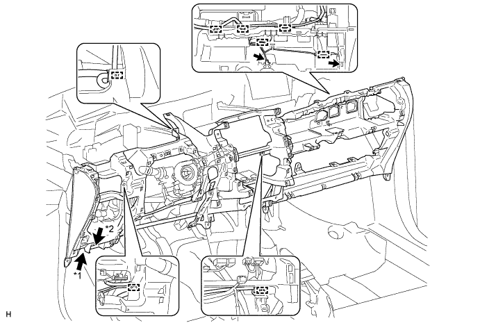
Text in Illustration *1 Hood Lock Control Cable *2 DLC3
-
-
for RHD:
-
Attach the 6 guides to install the lower instrument panel.
-
Install the 4 screws <D> and 2 bolts <B>.
-
Install the 11 bolts <C>.
Text in Illustration *1 Bolt <B> *2 Bolt <C> *3 Screw <D> - - -
Connect the connector and clamps.
-
Connect the hood lock control cable and DLC3.
Text in Illustration *1 Hood Lock Control Cable *2 DLC3
-
-
except Manual Transaxle:
-
Connect the connector and attach the clamp.
-
Install the shift lever assembly with the 4 nuts.
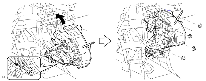
-
-
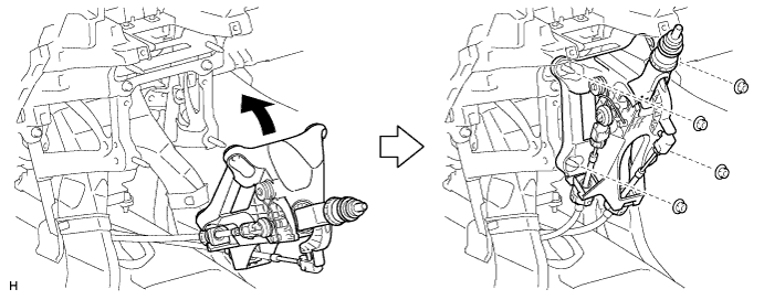
for Manual Transaxle:
-
Install the shift lever assembly with the 4 nuts.
-
-
-
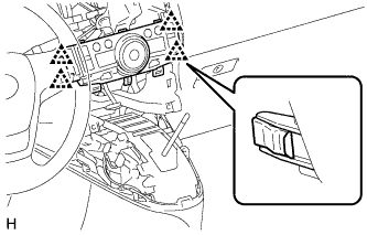
INSTALL LOWER NO. 1 INSTRUMENT PANEL FINISH PANEL
-
Attach the 4 clips to install the lower No. 1 instrument panel finish panel.
-
Connect the connector.
-
Install the screw <D>.
-
-
INSTALL FRONT NO. 2 CONSOLE BOX INSERT
-
Attach the 3 claws and guide to install the front No. 2 console box insert.
-
-
INSTALL FRONT NO. 1 CONSOLE BOX INSERT
-
Attach the 3 claws and guide to install the front No. 1 console box insert.
-
-
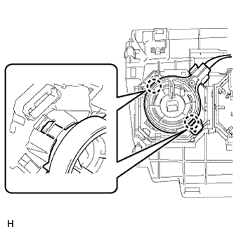
INSTALL AIR CONDITIONER CONTROL ASSEMBLY (for Automatic Air Conditioning System)
-
Connect the connector.
-
Attach the 4 clips to install the air conditioning control.
-
-
INSTALL CENTER INSTRUMENT CLUSTER FINISH PANEL ASSEMBLY (for Manual Air Conditioning System)
-
Attach the 2 claws to connect the air mix damper control cable sub-assembly.
-
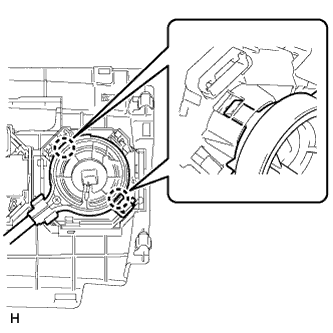
Attach the 2 claws to connect the No. 2 heater control cable sub-assembly.
-
Connect each connector.
-
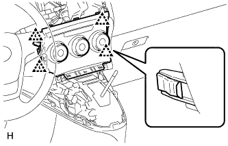
Attach the 4 clips to install the center instrument cluster finish panel assembly.
-
-
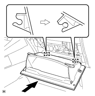
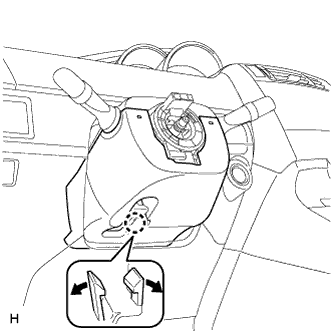
INSTALL GLOVE COMPARTMENT DOOR ASSEMBLY
-
Attach the 2 hinges to install the glove compartment door.
-
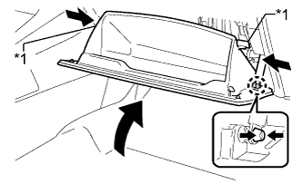
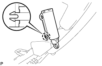
Attach the glove compartment door stopper to the glove compartment door as shown in the illustration.
-
While pushing in the sides of the glove compartment door as indicated by the arrows in the illustration, close the glove compartment door to engage the 2 stoppers.
Text in Illustration *1 Stopper
-
-
INSTALL NO. 2 INSTRUMENT PANEL UNDER COVER SUB-ASSEMBLY
-
Attach the 3 claws and guide to install the No. 2 instrument panel under cover.
-
-
INSTALL LOWER NO. 1 INSTRUMENT PANEL AIRBAG ASSEMBLY
-
Connect the connector.
Note
When handling the airbag connector, take care not to damage the airbag wire harness.
-
Attach the 6 claws to install the instrument panel airbag.
-
Install the 4 bolts.
- Torque:
- 10 N*m { 102 kgf*cm, 7 ft.*lbf }
-
-
INSTALL FUSE BOX OPENING COVER
-
for LHD:
-
Connect the connectors.
-
Attach the 6 clips and 4 claws to install the fuse box opening cover.
-
-
for RHD:
-
Connect the connectors.
-
Attach the 5 clips and 4 claws to install the fuse box opening cover.
-
-
-
INSTALL NO. 1 INSTRUMENT PANEL UNDER COVER SUB-ASSEMBLY
-
Attach the claw and guide to install the No. 1 instrument panel under cover.
-
Install the 2 screws <A>.
-
-
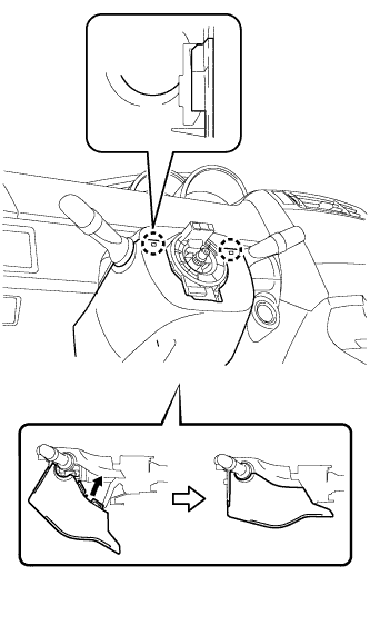
INSTALL UPPER STEERING COLUMN COVER
Note
If the steering column cover is installed in an incorrect order, it will not be possible to assemble the steering column cover.
-
Attach the claw and 2 pins to install the upper steering column cover.
-
-
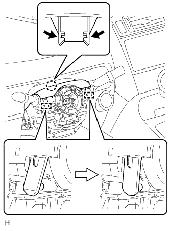
INSTALL LOWER STEERING COLUMN COVER
-
Attach the 2 claws and install the steering column lower cover as shown in the illustration.
-
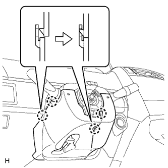
Attach the 4 claws.
-
Attach the claw.
Tech Tips
Press the area around the claw to attach it.
-
-
INSTALL STEERING WHEEL ASSEMBLY
-
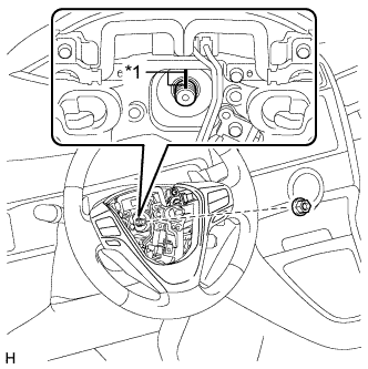
Text in Illustration *1 Matchmark Align the matchmarks on the steering wheel assembly and steering main shaft.
-
Install the steering wheel assembly set nut.
- Torque:
- 50 N*m { 510 kgf*cm, 37 ft.*lbf }
-
Connect the connectors to the spiral cable sub-assembly.
-
-
INSTALL STEERING PAD
-
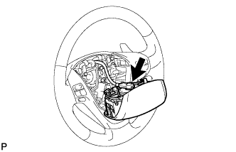
Support the steering pad with one hand.
-
Connect the connector to the steering pad.
Note
When handling the airbag connector, take care not to damage the airbag wire harness.
-
Connect the horn connector.
-
Attach the 2 springs to install the steering pad.
-
-
INSTALL BOX PANEL SUB-ASSEMBLY
-
Install the box panel sub-assembly Click here.
-
-
INSTALL INSTRUMENT PANEL SAFETY PAD SUB-ASSEMBLY
-
Install the instrument panel safety pad sub-assembly Click here.
-
-
CONNECT CABLE TO NEGATIVE BATTERY TERMINAL
Note
When disconnecting the cable, some systems need to be initialized after the cable is reconnected Click here.
-
CHECK SRS WARNING LIGHT
-
Check the SRS warning light Click here.
-