LOWER INSTRUMENT PANEL REMOVAL

Note
-
Use the same procedure for RHD and LHD vehicles.
-
The procedure listed below is for LHD vehicles.
-
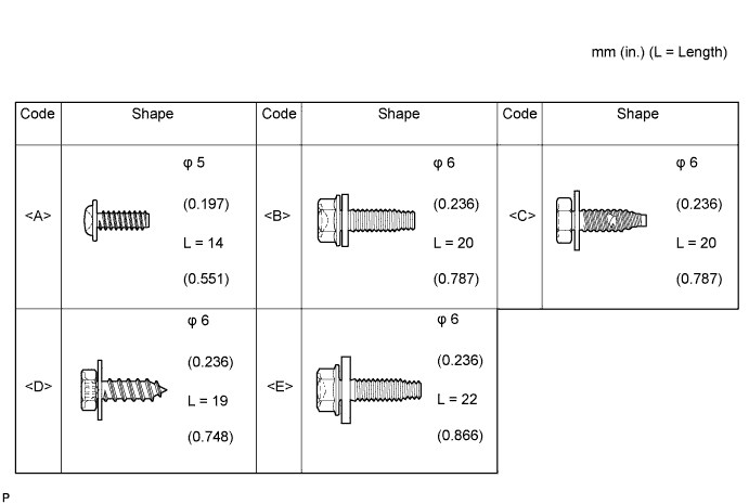
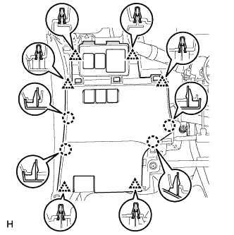
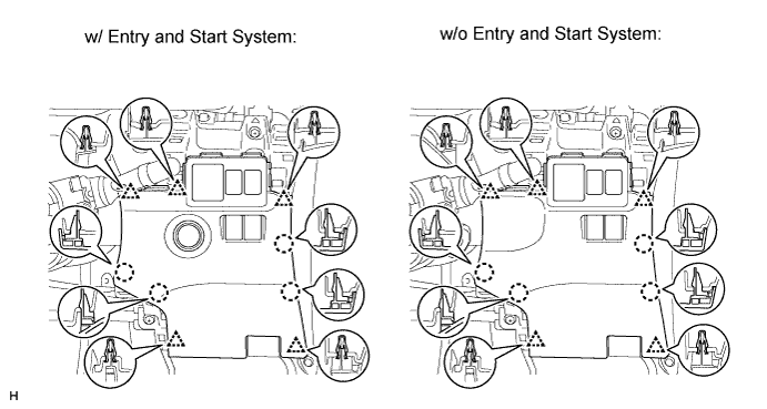
TABLE OF BOLT, SCREW AND NUT
Tech Tips
All bolts, screws and nuts relevant to installing and removing the instrument panel are shown along with their alphabet code in the table below.
-
PRECAUTION
Note
After turning the ignition switch off, waiting time may be required before disconnecting the cable from the battery terminal. Therefore, make sure to read the disconnecting the cable from the battery terminal notice before proceeding with work Click here.
-
DISCONNECT CABLE FROM NEGATIVE BATTERY TERMINAL
CAUTION:
Wait at least 90 seconds after disconnecting the cable from the negative (-) battery terminal to disable the SRS system.
Note
When disconnecting the cable some systems need to be initialized after the cable is reconnected Click here.
-
REMOVE INSTRUMENT PANEL SAFETY PAD SUB-ASSEMBLY
-
Remove the instrument panel safety pad sub-assembly Click here.
-
-
REMOVE BOX PANEL SUB-ASSEMBLY
-
Remove the box panel sub-assembly Click here.
-
-
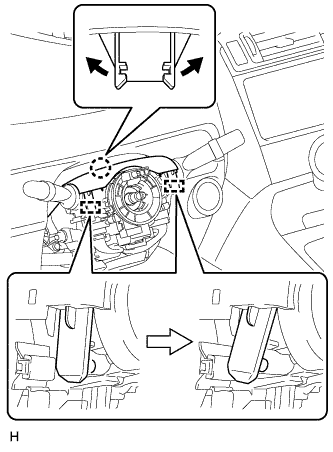
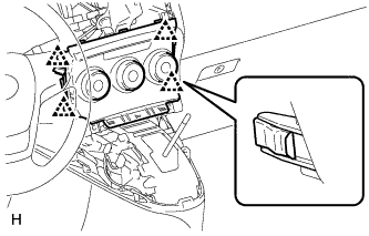
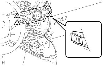
REMOVE STEERING PAD
-
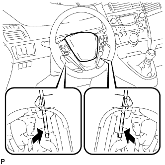
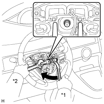
Using a screwdriver, detach the 2 springs.
-
Pull out the steering pad from the steering wheel as shown in the illustration and support the steering pad with one hand.
Note
When removing the steering pad, do not pull the airbag wire harness.
-
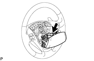
Disconnect the horn connector.
-
Disconnect the connector and remove the steering pad.
Note
When handling the airbag connector, take care not to damage the airbag wire harness.
-
-
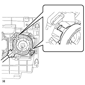
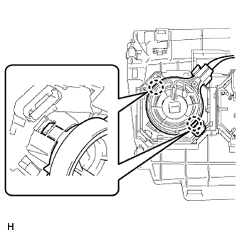
REMOVE STEERING WHEEL ASSEMBLY
-
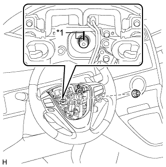
Text in Illustration *1 Matchmark Remove the steering wheel assembly set nut.
-
Put matchmarks on the steering wheel assembly and steering main shaft.
-
Disconnect the connectors from the spiral cable.
-
Text in Illustration *1 Turn *2 Hold Using SST, remove the steering wheel assembly.
- SST
- 09950-50013 ( 09951-05010, 09952-05010, 09953-05020, 09954-05021 )
Note
Apply a small amount of grease to the threads and tip of SST (09953-05020) before use.
-
-
REMOVE LOWER STEERING COLUMN COVER
Note
Removing the steering column cover in an incorrect order will cause the steering column cover to break.
-
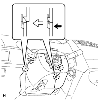
Push the right and left sides of the lower steering column cover and detach the 4 claws.
-
Insert fingers into the opening of the tilt lever of the lower steering column cover to detach the claw.
Tech Tips
Spread the claw to detach it.
-
Using a screwdriver, disengage the 2 claws.
-
Turn the steering column lower cover and remove the lower steering column cover as shown in the illustration.
-
-
REMOVE UPPER STEERING COLUMN COVER
-
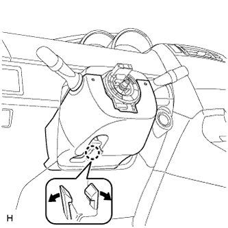
Detach the claw and 2 pins, and remove the upper steering column cover.
-
-
REMOVE NO. 1 INSTRUMENT PANEL UNDER COVER SUB-ASSEMBLY
-
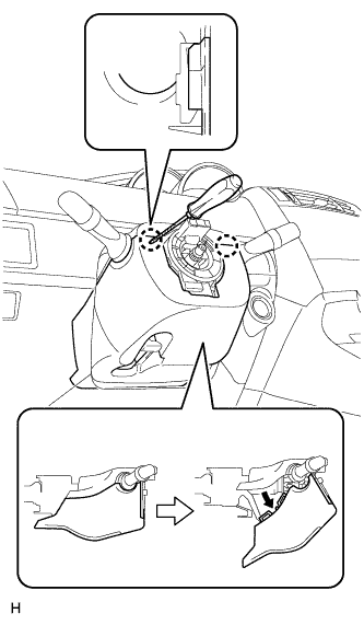
Remove the 2 screws <A>.
-
Detach the claw and guide, and remove the No. 1 instrument panel under cover.
-
-
REMOVE FUSE BOX OPENING COVER
-
for LHD:
-
Detach the 6 clips and 4 claws.
-
Disconnect the connectors and remove the fuse box opening cover.
-
-
for RHD:
-
Detach the 5 clips and 4 claws.
-
Disconnect the connectors and remove the fuse box opening cover.
-
-
-
REMOVE LOWER NO. 1 INSTRUMENT PANEL AIRBAG ASSEMBLY
-
Remove the 4 bolts.
-
Detach the 6 claws and remove the instrument panel airbag.
-
Disconnect the connector.
Note
When handling the airbag connector, take care not to damage the airbag wire harness.
-
-
REMOVE NO. 2 INSTRUMENT PANEL UNDER COVER SUB-ASSEMBLY
-
Detach the 3 claws and guide, and remove the No. 2 instrument panel under cover.
-
-
REMOVE GLOVE COMPARTMENT DOOR ASSEMBLY
-
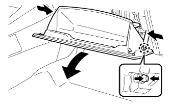
Push in the sides of the glove compartment door to release the 2 stoppers and open the glove compartment door until it is horizontal.
-
Detach the glove compartment door stopper from the glove compartment door as shown in the illustration.
-
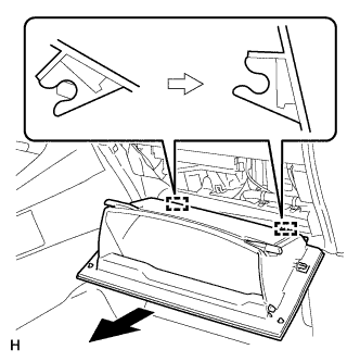
Pull the glove compartment door toward the rear of the vehicle to detach the 2 hinges and remove the glove compartment door.
-
-
REMOVE CENTER INSTRUMENT CLUSTER FINISH PANEL ASSEMBLY (for Manual Air Conditioning System)
-
Detach the 4 clips and remove the center instrument cluster finish panel assembly.
-
Disconnect each connector.
-
Detach the 2 claws and disconnect the No. 2 heater control cable sub-assembly.
-
Detach the 2 claws and disconnect the air mix damper control cable sub-assembly.
-
-
REMOVE AIR CONDITIONING CONTROL ASSEMBLY (for Automatic Air Conditioning System)
-
Detach the 4 clips.
-
Disconnect the connector and remove the air conditioning control.
-
-
REMOVE FRONT NO. 1 CONSOLE BOX INSERT
-
Detach the 3 claws and guide, and remove the front No. 1 console box insert.
-
-
REMOVE FRONT NO. 2 CONSOLE BOX INSERT
-
Detach the 3 claws and guide, and remove the front No. 2 console box insert.
-
-
REMOVE LOWER NO. 1 INSTRUMENT PANEL FINISH PANEL
-
Remove the screw <D>.
-
Disconnect the connector.
-
Detach the 4 clips and remove the lower No. 1 instrument panel finish panel.
-
-
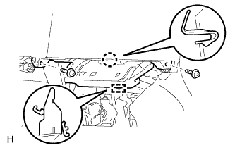
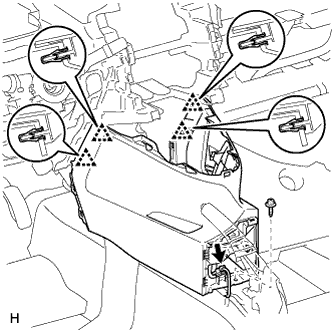
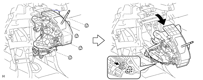
REMOVE LOWER INSTRUMENT PANEL SUB-ASSEMBLY
-
except Manual Transaxle:
-
Remove the 4 nuts.
-
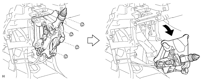
Disconnect the connector, detach the clamp and move the shift lever assembly as shown in the illustration.
-
-
for Manual Transaxle:
-
Remove the 4 nuts, and then move the shift lever assembly as shown in the illustration.
-
-
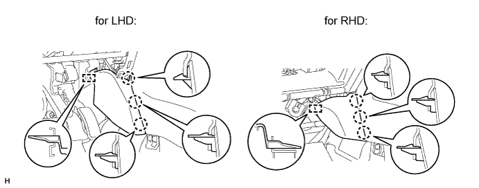
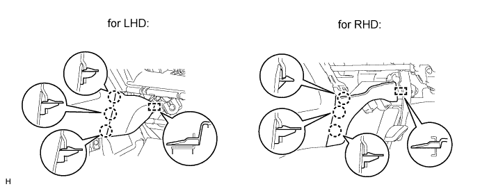
for LHD:
-
Disconnect the connectors and clamps.
-
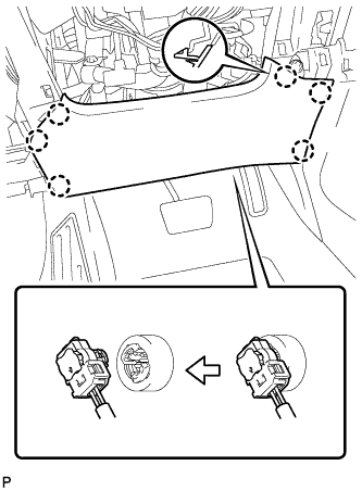
Disconnect the hood lock control cable and DLC3.
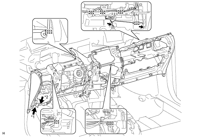
Text in Illustration *1 Hood Lock Control Cable *2 DLC3 -
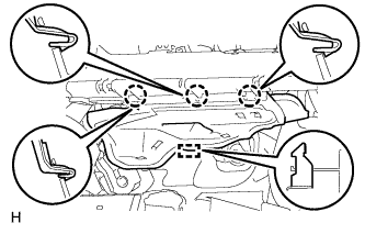
Remove the 4 screws <D> and 2 bolts <B>.
-
Remove the 11 bolts <C>.
-
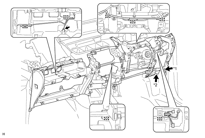
Detach the 6 guides and remove the lower instrument panel.
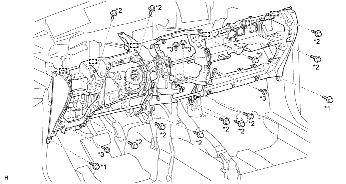
Text in Illustration *1 Bolt <B> *2 Bolt <C> *3 Screw <D> - -
-
-
for RHD:
-
Disconnect the connector and clamps.
-
Disconnect the hood lock control cable and DLC3.
Text in Illustration *1 Hood Lock Control Cable *2 DLC3 -
Remove the 4 screws <D> and 2 bolts <B>.
-
Remove the 11 bolts <C>.
-
Detach the 6 guides and remove the lower instrument panel.
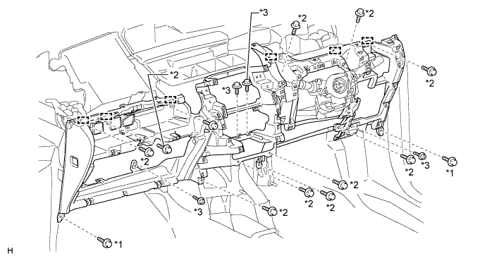
Text in Illustration *1 Bolt <B> *2 Bolt <C> *3 Screw <D> - -
-
-
-
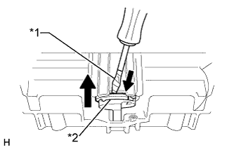
REMOVE GLOVE COMPARTMENT DOOR STOPPER SUB-ASSEMBLY
-
Detach the claw and remove the glove compartment door stopper.
-
-
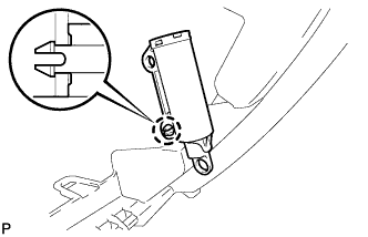
REMOVE GLOVE COMPARTMENT DOOR LOCK CYLINDER ASSEMBLY (for RHD)
Text in Illustration *1 Protective Tape *2 Stopper
-
Using a screwdriver, push the stopper of the glove compartment door lock cylinder as shown in the illustration and remove the glove compartment door lock cylinder in the direction of the arrow in the illustration.
Tech Tips
Tape the screwdriver tip before use.
-