METER / GAUGE SYSTEM Speed Signal Circuit
DESCRIPTION
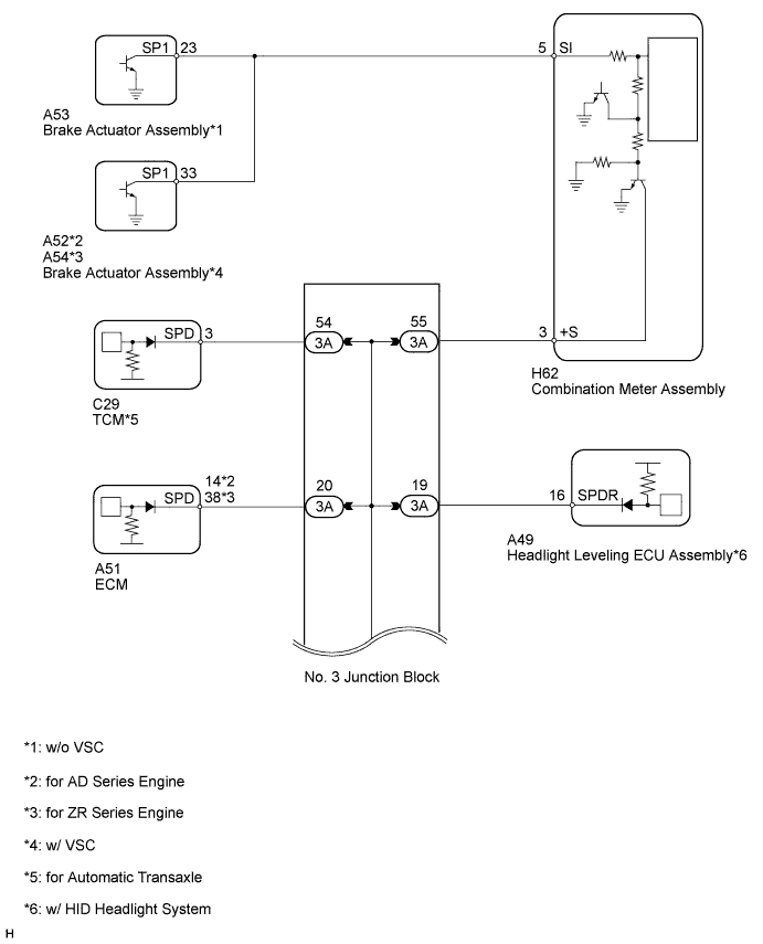
The vehicle speed signal consists of pulses sent to the combination meter assembly from the skid control ECU.
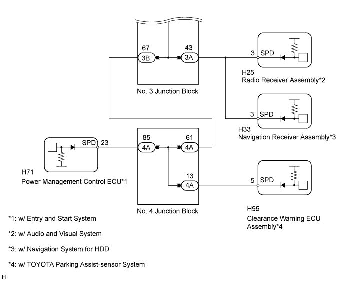
WIRING DIAGRAM
INSPECTION PROCEDURE
PROCEDURE
-
CHECK ECU TERMINAL VOLTAGE (INPUT VOLTAGE)
-
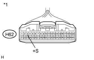
Text in Illustration *1 Front view of wire harness connector
(to Combination Meter Assembly)
Disconnect the H62 meter connector.
-
Measure the voltage according to the value(s) in the table below.
Standard Voltage Tester Connection Switch Condition Specified Condition H62-3 (+S) - Body ground Ignition switch ON 4.5 to 14 V
NG 
CHECK HARNESS AND CONNECTOR (COMBINATION METER ASSEMBLY - NO. 3 JUNCTION BLOCK) Click here
OK 
-
-
CHECK COMBINATION METER ASSEMBLY (OUTPUT VOLTAGE)
-
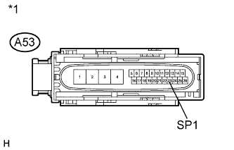
Text in Illustration *1 Front view of wire harness connector
(to Brake Actuator Assembly)
w/o VSC:
-
Disconnect the A53 brake actuator connector.
-
Measure the voltage according to the value(s) in the table below.
Standard Voltage Tester Connection Switch Condition Specified Condition A53-23 (SP1) - Body ground Ignition switch ON 11 to 14 V
-
-
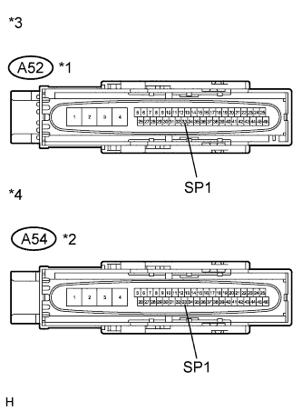
Text in Illustration *1 for AD Series Engine *2 for ZR Series Engine *3 Front view of wire harness connector
(to Brake Actuator Assembly)
*4 Front view of wire harness connector
(to Brake Actuator Assembly)
w/ VSC:
-
Disconnect the A52*1 or A54*2 brake actuator connector.
*1: for AD Series Engine
*2: for ZR Series Engine
-
Measure the voltage according to the value(s) in the table below.
Standard Voltage for AD Series Engine Tester Connection Switch Condition Specified Condition A52-33 (SP1) - Body ground Ignition switch ON 11 to 14 V for ZR Series Engine Tester Connection Switch Condition Specified Condition A54-33 (SP1) - Body ground Ignition switch ON 11 to 14 V
-
NG
CHECK HARNESS AND CONNECTOR (COMBINATION METER ASSEMBLY - SKID CONTROL ECU) Click here
OK
-
-
CHECK COMBINATION METER ASSEMBLY (SPEED SIGNAL)
-
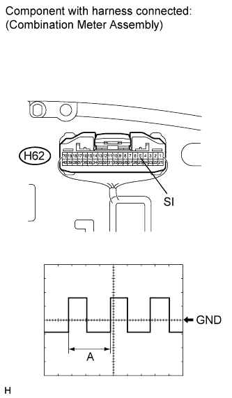
Check the input waveform.
-
Reconnect the H62 meter connector.
-
Remove the combination meter assembly with the connector(s) still connected.
-
Connect an oscilloscope to terminal H62-5 (SI) and body ground.
-
Turn the ignition switch to ON.
-
Check the signal waveform according to the condition(s) in the table below.
Measurement Condition Item Condition Terminal No. (Symbol) H62-5 (SI) - Body ground Tool setting 5 V/DIV., 20 ms./DIV. Condition Being driven at approx. 20 km/h (12 mph) OK The waveform displayed is as shown in the illustration. Tech Tips
When the system is functioning normally, one wheel revolution generates 4 pulses. As the vehicle speed increases, the width indicated by (A) in the illustration narrows.
Result Result Proceed to OK A NG (w/o VSC) B NG (w/ VSC) C
-
B 
REPLACE BRAKE ACTUATOR ASSEMBLY Click here
C
REPLACE BRAKE ACTUATOR ASSEMBLY Click here
A 
REPLACE COMBINATION METER ASSEMBLY Click here
-
-
CHECK HARNESS AND CONNECTOR (COMBINATION METER ASSEMBLY - SKID CONTROL ECU)
-
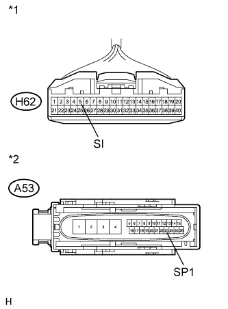
Text in Illustration *1 Front view of wire harness connector
(to Combination Meter Assembly)
*2 Front view of wire harness connector
(to Brake Actuator Assembly)
w/o VSC:
-
Disconnect the H62 meter connector.
-
Disconnect the A53 brake actuator connector.
-
Measure the resistance according to the value(s) in the table below.
Standard Resistance Tester Connection Condition Specified Condition H62-5 (SI) - A53-23 (SP1) Always Below 1 Ω A53-23 (SP1) - Body ground Always 10 kΩ or higher
-
-
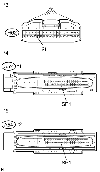
Text in Illustration *1 for AD Series Engine *2 for ZR Series Engine *3 Front view of wire harness connector
(to Combination Meter Assembly)
*4 Front view of wire harness connector
(to Brake Actuator Assembly)
*5 Front view of wire harness connector
(to Brake Actuator Assembly)
w/ VSC:
-
Disconnect the H62 meter connector.
-
Disconnect the A52*1 or A54*2 brake actuator connector.
*1: for AD Series Engine
*2: for ZR Series Engine
-
Measure the resistance according to the value(s) in the table below.
Standard Resistance for AD Series Engine Tester Connection Condition Specified Condition H62-5 (SI) - A52-33 (SP1) Always Below 1 Ω A52-33 (SP1) - Body ground Always 10 kΩ or higher for ZR Series Engine Tester Connection Condition Specified Condition H62-5 (SI) - A54-33 (SP1) Always Below 1 Ω A54-33 (SP1) - Body ground Always 10 kΩ or higher
-
NG
REPAIR OR REPLACE HARNESS OR CONNECTOR
OK
REPLACE COMBINATION METER ASSEMBLY Click here
-
-
CHECK HARNESS AND CONNECTOR (COMBINATION METER ASSEMBLY - NO. 3 JUNCTION BLOCK)
-
Disconnect the H62 meter connector.
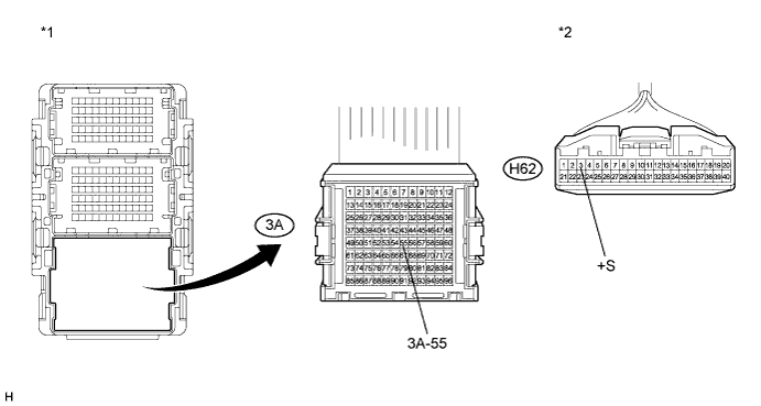
-
Disconnect the 3A junction block connector.
-
Measure the resistance according to the value(s) in the table below.
Standard Resistance Tester Connection Condition Specified Condition H62-3 (+S) - 3A-55 Always Below 1 Ω H62-3 (+S) - Body ground Always 10 kΩ or higher Text in Illustration *1 Front view of wire harness connector
(to No. 3 Junction Block)
*2 Front view of wire harness connector
(to Combination Meter Assembly)
NG
REPAIR OR REPLACE HARNESS OR CONNECTOR
OK
-
-
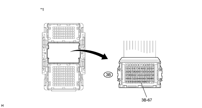
CHECK POWER MANAGEMENT CONTROL ECU
Note
For vehicles with neither the entry and start system nor the TOYOTA parking assist-sensor system, go to "Check Radio Receiver Assembly".
-
Disconnect the 3B junction block connector.
-
Measure the voltage according to the value(s) in the table below.
Standard Voltage Tester Connection Switch Condition Specified Condition 3B-67 - Body ground Ignition switch ON 4.5 to 14 V Text in Illustration *1 Front view of wire harness connector
(to No. 3 Junction Block)
- -
NG
CHECK HARNESS AND CONNECTOR (NO. 3 JUNCTION BLOCK - NO. 4 JUNCTION BLOCK) Click here
OK
-
-
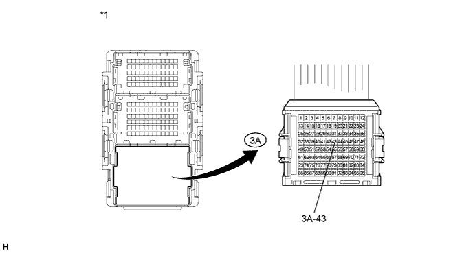
CHECK RADIO RECEIVER ASSEMBLY
Note
For vehicles with a navigation system, go to "Check Navigation Receiver Assembly".
-
Disconnect the 3A junction block connector.
-
Measure the voltage according to the value(s) in the table below.
Standard Voltage Tester Connection Switch Condition Specified Condition 3A-43 - Body ground Ignition switch ON 4.5 to 14 V Text in Illustration *1 Front view of wire harness connector
(to No. 3 Junction Block)
- -
NG
CHECK HARNESS AND CONNECTOR (RADIO RECEIVER ASSEMBLY CIRCUIT) Click here
OK
-
-
CHECK NAVIGATION RECEIVER ASSEMBLY
Note
For vehicles with an audio and visual system, go to "Check Headlight Leveling ECU".
-
Disconnect the 3A junction block connector.
-
Measure the voltage according to the value(s) in the table below.
Standard Voltage Tester Connection Switch Condition Specified Condition 3A-43 - Body ground Ignition switch ON 4.5 to 14 V Text in Illustration *1 Front view of wire harness connector
(to No. 3 Junction Block)
- -
NG
CHECK HARNESS AND CONNECTOR (NAVIGATION RECEIVER ASSEMBLY CIRCUIT) Click here
OK
-
-
CHECK HEADLIGHT LEVELING ECU ASSEMBLY
Note
For vehicles without an HID headlight system, go to "Check TCM".
-
Disconnect the 3A junction block connector.

-
Measure the voltage according to the value(s) in the table below.
Standard Voltage Tester Connection Switch Condition Specified Condition 3A-19 - Body ground Ignition switch ON 4.5 to 14 V Text in Illustration *1 Front view of wire harness connector
(to No. 3 Junction Block)
- -
NG
CHECK HARNESS AND CONNECTOR (HEADLIGHT LEVELING ECU ASSEMBLY CIRCUIT) Click here
OK
-
-
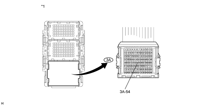
CHECK TCM
Note
For vehicles with a manual transaxle or CVT, go to "Check ECM".
-
Disconnect the 3A junction block connector.
-
Measure the voltage according to the value(s) in the table below.
Standard Voltage Tester Connection Switch Condition Specified Condition 3A-54 - Body ground Ignition switch ON 4.5 to 14 V Text in Illustration *1 Front view of wire harness connector
(to No. 3 Junction Block)
- -
NG
CHECK HARNESS AND CONNECTOR (TCM CIRCUIT) Click here
OK
-
-
CHECK ECM
-
Disconnect the 3A junction block connector.

-
Measure the voltage according to the value(s) in the table below.
Standard Voltage Tester Connection Switch Condition Specified Condition 3A-20 - Body ground Ignition switch ON 4.5 to 14 V Text in Illustration *1 Front view of wire harness connector
(to No. 3 Junction Block)
- -
NG
CHECK HARNESS AND CONNECTOR (ECM CIRCUIT) Click here
OK
REPLACE NO. 3 JUNCTION BLOCK
-
-
CHECK HARNESS AND CONNECTOR (NO. 3 JUNCTION BLOCK - NO. 4 JUNCTION BLOCK)
-
Disconnect the 3B junction block connector.
-
Disconnect the 4A junction block connector.
-
Measure the resistance according to the value(s) in the table below.
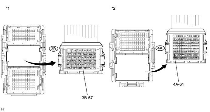
Standard Resistance Tester Connection Condition Specified Condition 3B-67 - 4A-61 Always Below 1 Ω 3B-67 - Body ground Always 10 kΩ or higher Text in Illustration *1 Front view of wire harness connector
(to No. 3 Junction Block)
*2 Front view of wire harness connector
(to No. 4 Junction Block)
NG
REPAIR OR REPLACE HARNESS OR CONNECTOR
OK
-
-
CHECK NO. 4 JUNCTION BLOCK
-
Disconnect the 4A junction block connector.
-
Measure the voltage according to the value(s) in the table below.
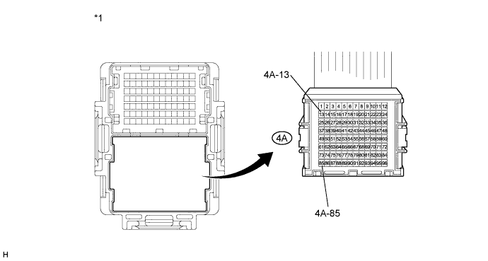
Standard Voltage Tester Connection Switch Condition Specified Condition 4A-85 - Body ground Ignition switch ON 4.5 to 14 V 4A-13 - Body ground Ignition switch ON 4.5 to 14 V Text in Illustration *1 Front view of wire harness connector
(to No. 4 Junction Block)
- - Result Result Proceed to NG (4A-85) A NG (4A-13) B OK C
B
CHECK HARNESS AND CONNECTOR (CLEARANCE WARNING ECU CIRCUIT) Click here
C
REPLACE NO. 4 JUNCTION BLOCK
A
-
-
CHECK HARNESS AND CONNECTOR (POWER MANAGEMENT CONTROL ECU CIRCUIT)
-
Disconnect the 4A junction block connector.
-
Disconnect the H71 power management control ECU connector.
-
Measure the resistance according to the value(s) in the table below.
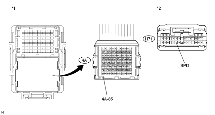
Standard Resistance Tester Connection Condition Specified Condition H71-23 (SPD) - 4A-85 Always Below 1 Ω 4A-85 - Body ground Always 10 kΩ or higher Text in Illustration *1 Front view of wire harness connector
(to No. 4 Junction Block)
*2 Front view of wire harness connector
(to Power Management Control ECU)
Result Result Proceed to OK (for LHD) A OK (for RHD) B NG C
B
REPLACE POWER MANAGEMENT CONTROL ECU Click here
C
REPAIR OR REPLACE HARNESS OR CONNECTOR
A
REPLACE POWER MANAGEMENT CONTROL ECU Click here
-
-
CHECK HARNESS AND CONNECTOR (RADIO RECEIVER ASSEMBLY CIRCUIT)
-
Disconnect the 3A junction block connector.
-
Disconnect the H25 radio receiver connector.
-
Measure the resistance according to the value(s) in the table below.
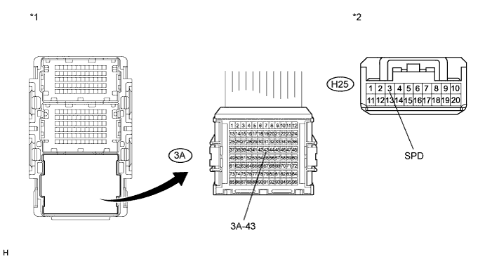
Standard Resistance Tester Connection Condition Specified Condition H25-3 (SPD) - 3A-43 Always Below 1 Ω 3A-43 - Body ground Always 10 kΩ or higher Text in Illustration *1 Front view of wire harness connector
(to No. 3 Junction Block)
*2 Front view of wire harness connector
(to Radio Receiver Assembly)
NG
REPAIR OR REPLACE HARNESS OR CONNECTOR
OK
REPLACE RADIO RECEIVER ASSEMBLY Click here
-
-
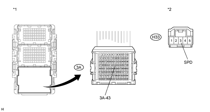
CHECK HARNESS AND CONNECTOR (NAVIGATION RECEIVER ASSEMBLY CIRCUIT)
-
Disconnect the 3A junction block connector.
-
Disconnect the H33 navigation receiver connector.
-
Measure the resistance according to the value(s) in the table below.
Standard Resistance Tester Connection Condition Specified Condition H33-3 (SPD) - 3A-43 Always Below 1 Ω 3A-43 - Body ground Always 10 kΩ or higher Text in Illustration *1 Front view of wire harness connector
(to No. 3 Junction Block)
*2 Front view of wire harness connector
(to Navigation Receiver Assembly)
NG
REPAIR OR REPLACE HARNESS OR CONNECTOR
OK
REPLACE NAVIGATION RECEIVER ASSEMBLY Click here
-
-
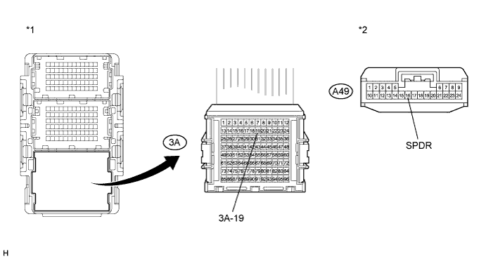
CHECK HARNESS AND CONNECTOR (HEADLIGHT LEVELING ECU ASSEMBLY CIRCUIT)
-
Disconnect the 3A junction block connector.
-
Disconnect the A49 headlight leveling ECU connector.
-
Measure the resistance according to the value(s) in the table below.
Standard Resistance Tester Connection Condition Specified Condition A49-16 (SPDR) - 3A-19 Always Below 1 Ω 3A-19 - Body ground Always 10 kΩ or higher Text in Illustration *1 Front view of wire harness connector
(to No. 3 Junction Block)
*2 Front view of wire harness connector
(to Headlight Leveling ECU)
Result Result Proceed to OK (for LHD) A OK (for RHD) B NG C
B
REPLACE HEADLIGHT LEVELING ECU ASSEMBLY Click here
C
REPAIR OR REPLACE HARNESS OR CONNECTOR
A
REPLACE HEADLIGHT LEVELING ECU ASSEMBLY Click here
-
-
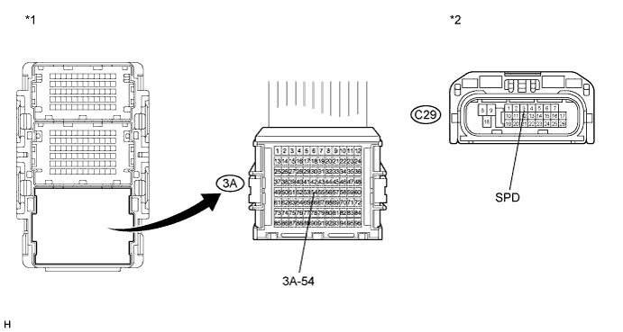
CHECK HARNESS AND CONNECTOR (TCM CIRCUIT)
-
Disconnect the 3A junction block connector.
-
Disconnect the C29 TCM connector.
-
Measure the resistance according to the value(s) in the table below.
Standard Resistance Tester Connection Condition Specified Condition C29-3 (SPD) - 3A-54 Always Below 1 Ω 3A-54 - Body ground Always 10 kΩ or higher Text in Illustration *1 Front view of wire harness connector
(to No. 3 Junction Block)
*2 Front view of wire harness connector
(to TCM)
NG
REPAIR OR REPLACE HARNESS OR CONNECTOR
OK
REPLACE TCM Click here
-
-
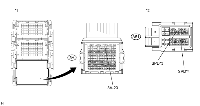
CHECK HARNESS AND CONNECTOR (ECM CIRCUIT)
-
Disconnect the 3A junction block connector.
-
Disconnect the A51 ECM connector.
-
Measure the resistance according to the value(s) in the table below.
Standard Resistance for AD Series Engine Tester Connection Condition Specified Condition A51-14 (SPD) - 3A-20 Always Below 1 Ω 3A-20 - Body ground Always 10 kΩ or higher for ZR Series Engine Tester Connection Condition Specified Condition A51-38 (SPD) - 3A-20 Always Below 1 Ω 3A-20 - Body ground Always 10 kΩ or higher Text in Illustration *1 Front view of wire harness connector
(to No. 3 Junction Block)
*2 Front view of wire harness connector
(to ECM)
*3 for AD Series Engine *4 for ZR Series Engine Result Result Proceed to NG A OK (for 1ZR-FAE) B OK (for 2ZR-FAE) C OK (for 1AD-FTV) D OK (for 2AD-FHV) E
B
REPLACE ECM Click here
C
REPLACE ECM Click here
D
REPLACE ECM Click here
E
REPLACE ECM Click here
A
REPAIR OR REPLACE HARNESS OR CONNECTOR
-
-
CHECK HARNESS AND CONNECTOR (CLEARANCE WARNING ECU CIRCUIT)
-
Disconnect the 4A junction block connector.
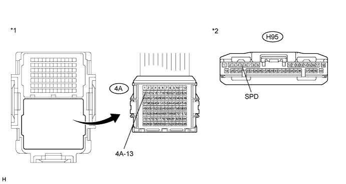
-
Disconnect the H95 clearance warning ECU connector.
-
Measure the resistance according to the value(s) in the table below.
Standard Resistance Tester Connection Condition Specified Condition H95-5 (SPD) - 4A-13 Always Below 1 Ω 4A-13 - Body ground Always 10 kΩ or higher Text in Illustration *1 Front view of wire harness connector
(to No. 4 Junction Block)
*2 Front view of wire harness connector
(to Clearance Warning ECU)
NG
REPAIR OR REPLACE HARNESS OR CONNECTOR
OK
REPLACE CLEARANCE WARNING ECU ASSEMBLY Click here
-