SPEED LIMITER SYSTEM Speed Limiter System does not Operate
DESCRIPTION
When the speed limiter main switch is turned on, the ECM illuminates the speed limiter indicator light and activates the speed limiter system. Each control of the speed limiter system can be activated by operating the cruise control switch. When the cruise control system is operating, the speed limiter system will not activate.
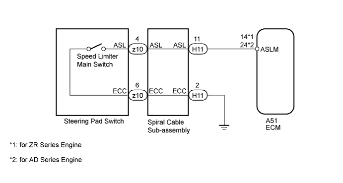
WIRING DIAGRAM
INSPECTION PROCEDURE
PROCEDURE
-
CHECK CRUISE CONTROL SYSTEM
-
Turn the ignition switch to ON.
-
Turn the cruise control switch on.
-
Check the operation of each function by operating the cruise control switch Click here.
OK Each function of the cruise control system operates normally.
NG 
GO TO CRUISE CONTROL SYSTEM Click here
OK 
-
-
READ VALUE USING INTELLIGENT TESTER (SPEED LIMITER MAIN SWITCH)
-
Use the Data List to check if the speed limiter main switch is functioning properly.
Cruise Control Tester Display Measurement Item/Range Normal Condition Diagnostic Note ASL Main Switch Speed limiter main switch signal / ON or OFF ON: Speed limiter main switch on
OFF: Speed limiter main switch off
- OK On screen, item changes between ON and OFF according to above chart.
NG 
INSPECT SPIRAL CABLE SUB-ASSEMBLY Click here
OK
-
-
CHECK FOR DTC (CRUISE CONTROL SYSTEM)
-
Check for DTCs Click here.
OK DTCs P0500 and P0503 are not output. Result Result Proceed to OK (for 1ZR-FAE) A OK (for 2ZR-FAE) B OK (for 1AD-FTV) C OK (for 2AD-FHV) D NG E
B
REPLACE ECM Click here
C
REPLACE ECM Click here
D
REPLACE ECM Click here
E
GO TO CRUISE CONTROL SYSTEM Click here
A 
REPLACE ECM Click here
-
-
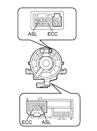
INSPECT SPIRAL CABLE SUB-ASSEMBLY
-
If there are any defects as follows, replace the spiral cable with a new one: scratches, cracks, dents or chips on the connector or spiral cable.
-
Check spiral cable.
-
Set the spiral cable to the center position Click here.
-
Rotate the spiral cable 2.5 times clockwise and measure the resistance according to the value(s) in the table below. Then rotate the spiral cable 5 times counterclockwise and measure the resistance according to the value(s) in the table below.
Note
As the spiral cable may break, do not rotate the spiral cable more than the specified amount.
Standard Resistance Tester Connection Condition Specified Condition 11 (ASL) - 4 (ASL) Always Below 1 Ω 2 (ECC) - 6 (ECC) -
Set the spiral cable to the center position and rotate the spiral cable 2.5 times clockwise. Then, while rotating the spiral cable 5 times counterclockwise, measure the resistance according to the value(s) in the table below.
Standard Resistance Tester Connection Condition Specified Condition 11 (ASL) - 4 (ASL) Always Below 1 Ω 2 (ECC) - 6 (ECC)
-
NG
REPLACE SPIRAL CABLE SUB-ASSEMBLY Click here
OK
-
-
INSPECT STEERING PAD SWITCH ASSEMBLY (SPEED LIMITER MAIN SWITCH)
-
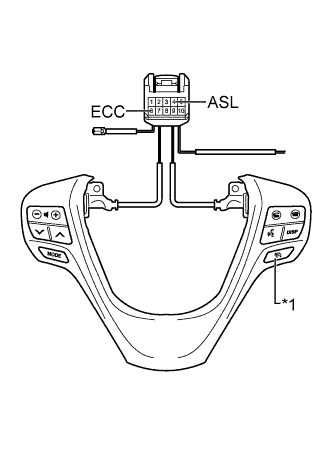
Text in Illustration *1 Speed Limiter Main Switch Remove the steering pad switch Click here.
-
Measure the resistance according to the value(s) in the table below.
Standard Resistance Tester Connection Switch Condition Specified Condition 4 (ASL) - 6 (ECC) Speed limiter main switch on Below 2.5 Ω Speed limiter main switch off 1 MΩ or higher
NG
REPLACE STEERING PAD SWITCH ASSEMBLY Click here
OK
-
-
CHECK HARNESS AND CONNECTOR (SPIRAL CABLE - ECM AND BODY GROUND)
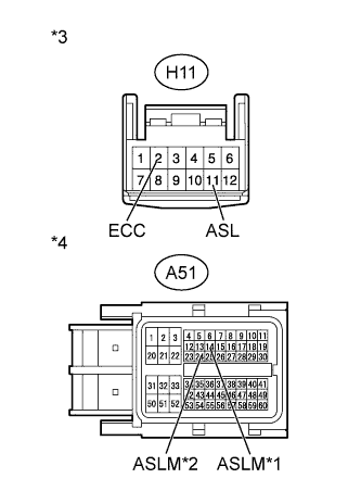
Text in Illustration *1 for ZR Series Engine *2 for AD Series Engine *3 Front view of wire harness connector
(to Spiral Cable)
*4 Front view of wire harness connector
(to ECM)
-
Disconnect the H11 spiral cable connector.
-
Disconnect the A51 ECM connector.
-
Measure the resistance according to the value(s) in the table below.
Standard Resistance for ZR Series Engine Tester Connection Condition Specified Condition H11-11 (ASL) - A51-14 (ASLM) Always Below 1 Ω H11-2 (ECC) - Body ground H11-11 (ASL) - Body ground Always 10 kΩ or higher for AD Series Engine Tester Connection Condition Specified Condition H11-11 (ASL) - A51-24 (ASLM) Always Below 1 Ω H11-2 (ECC) - Body ground H11-11 (ASL) - Body ground Always 10 kΩ or higher Result Result Proceed to OK (for 1ZR-FAE) A OK (for 2ZR-FAE) B OK (for 1AD-FTV) C OK (for 2AD-FHV) D NG E
B
REPLACE ECM Click here
C
REPLACE ECM Click here
D
REPLACE ECM Click here
E
REPAIR OR REPLACE HARNESS OR CONNECTOR
A
REPLACE ECM Click here
-