INTAKE MANIFOLD INSTALLATION

-
INSTALL ENGINE COVER JOINT
-
Install the engine cover joint.
- Torque:
- 8.0 N*m { 82 kgf*cm, 71 in.*lbf }
-
-
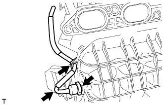
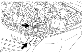
INSTALL NO. 1 GAS FILTER
-
Using a 24 mm deep socket wrench, install the gas filter to the intake manifold.
- Torque:
- 17 N*m { 173 kgf*cm, 13 ft.*lbf }
-
Connect the air hose.
-
-
INSTALL INTAKE MANIFOLD
-
Using an E6 "TORX" socket wrench, install the 2 stud bolts to the intake manifold.
- Torque:
- 5.0 N*m { 51 kgf*cm, 44 in.*lbf }
-
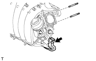
Install the wire harness clamp bracket to the intake manifold with the bolt.
- Torque:
- 15 N*m { 153 kgf*cm, 11 ft.*lbf }
-
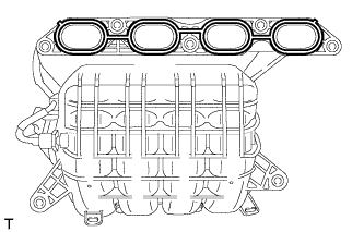
Install a new gasket to the intake manifold.
-
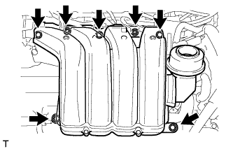
Install the intake manifold and intake manifold stay with the 5 bolts and 2 nuts.
- Torque:
- 28 N*m { 286 kgf*cm, 21 ft.*lbf }
-
Connect the fuel vapor feed hose and ventilation hose.
-
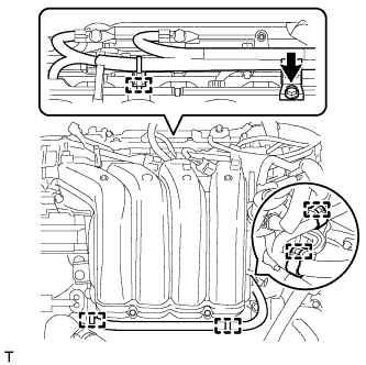
Attach the 5 clamps to the intake manifold.
-
Install the wire harness clamp bracket with the bolt.
- Torque:
- 10 N*m { 102 kgf*cm, 7 ft.*lbf }
-
-
INSTALL NO. 1 VACUUM SWITCHING VALVE ASSEMBLY
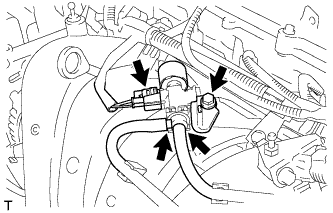
-
Install the vacuum switching valve with the bolt.
- Torque:
- 10 N*m { 102 kgf*cm, 7 ft.*lbf }
-
Connect the connector and 2 vacuum hoses.
-
-
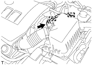
INSTALL VACUUM SENSOR ASSEMBLY
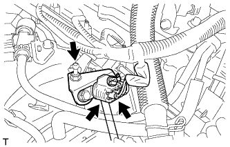
-
Connect the air hose to the vacuum sensor.
-
Install the vacuum sensor with the bolt.
- Torque:
- 8.0 N*m { 82 kgf*cm, 71 in.*lbf }
-
Connect the vacuum sensor connector.
-
-
INSTALL THROTTLE BODY ASSEMBLY
-
Install a new gasket to the intake manifold.
-
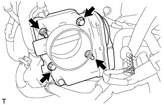
Install the throttle body with the 2 bolts and 2 nuts.
- Torque:
- 10 N*m { 102 kgf*cm, 7 ft.*lbf }
-
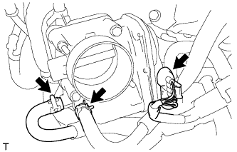
Connect the throttle body connector and 2 water hoses.
-
-
INSTALL AIR CLEANER CAP SUB-ASSEMBLY
-
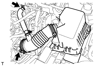
Connect the air cleaner cap with the band.
-
Connect the PCV hose.
-
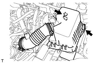
Connect the 2 clamps.
-
Attach the 2 clamps and connect the wire harness.
-
Connect the mass air flow meter connector.
-
-
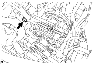
INSTALL GENERATOR ASSEMBLY
-
Install the wire harness clamp bracket with the bolt.
- Torque:
- 8.4 N*m { 85 kgf*cm, 74 in.*lbf }
-
Temporarily install the generator with the bolt.
-
Temporarily install the adjusting bar with the 2 bolts.
-
Tighten the bolt.
- Torque:
- 25 N*m { 255 kgf*cm, 18 ft.*lbf }
-
Install the wire harness to terminal B with the nut and install the terminal cap.
- Torque:
- 9.8 N*m { 100 kgf*cm, 87 in.*lbf }
-
Connect the connector and attach the wire harness clamp.
-
-
INSTALL V-RIBBED BELT
-
Temporarily install the V-ribbed belt.
-
-
ADJUST V-RIBBED BELT
-
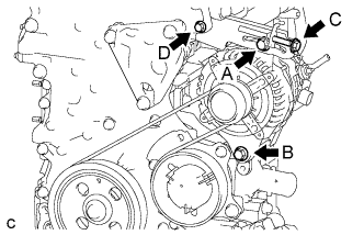
Turn bolt C to adjust the tension of the V-ribbed belt.
-
Tighten bolts A and B.
- Torque:
- for bolt A
- 25 N*m { 255 kgf*cm, 18 ft.*lbf }
- for bolt B
- 43 N*m { 438 kgf*cm, 32 ft.*lbf }
Note
Do not loosen bolt D.
-
-
INSPECT V-RIBBED BELT
-

Check the belt for wear, cracks or other signs of damage.
If any of the following defects is found, replace the V-ribbed belt.
-
The belt is cracked.
-
The belt is worn out to the extent that the cords are exposed.
-
The belt has chunks missing from the ribs.
-
-
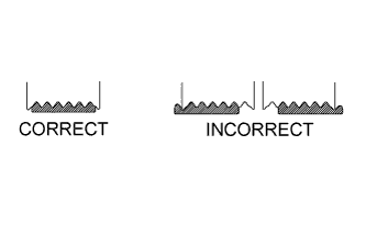
Check that the belt fits properly in the ribbed grooves.
Tech Tips
Check with your hand to confirm that the belt has not slipped out of the grooves on the bottom to the pulley. If it has slipped out, replace the V-ribbed belt. Install a new V-ribbed belt correctly.
-
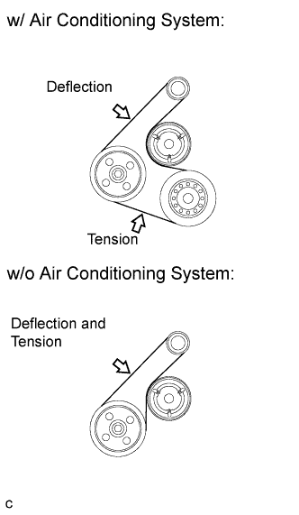
Check the V-ribbed belt deflection and tension.
Standard Deflection Item Specified Condition New belt 7.0 to 8.2 mm (0.276 to 0.323 in.) Used belt 7.6 to 10.0 mm (0.299 to 0.394 in.) Standard Tension Item Specified Condition New belt 700 to 800 N (70 to 80 kgf, 157.4 to 179.8 lbf) Used belt 550 to 750 N (55 to 75 kgf, 123.6 to 168.6 lbf) Tech Tips
-
When inspecting the V-ribbed belt deflection, apply 98 N (10 kgf, 22.0 lbf) of tensile force to it.
-
Check the V-ribbed belt deflection at the specified point.
-
V-ribbed belt tension and deflection should be checked after 2 revolutions of engine cranking.
-
Measure the belt tension when the engine is cold.
-
When adjusting the belt, be sure to adjust it so that the tension is as close as possible to the median of the specified range.
-
When replacing the belt with a new one, be sure to perform the following after adjusting the belt: idle the engine for 5 minutes, and then adjust the belt to the specified value for a new belt after the engine has cooled.
-
When inspecting a belt which has been used for over 5 minutes, apply the used belt specifications.
-
When using a belt tension gauge, confirm its accuracy by using a master gauge first.
-
-
-
INSTALL REAR ENGINE UNDER COVER RH
-
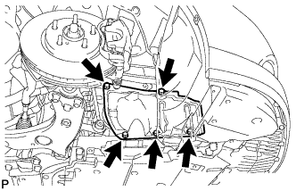
Install the under cover RH with the 5 clips.
-
-
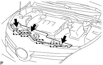
INSTALL NO. 2 CYLINDER HEAD COVER
-
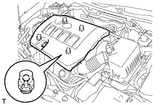
Attach the 4 clips to install the cover.
Note
-
Be sure to attach the clips securely.
-
Do not apply excessive force or hit the cover to attach the clips. This may cause the cover to break.
-
-
-
CONNECT CABLE TO NEGATIVE BATTERY TERMINAL
Note
When disconnecting the cable, some systems need to be initialized after the cable is reconnected Click here.
-
ADD ENGINE COOLANT
-
Tighten the radiator drain cock plug.
-
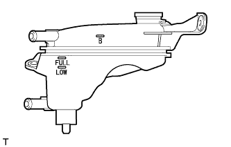
Add TOYOTA Super Long Life Coolant (SLLC) through the radiator reservoir filler opening until the coolant reaches the B line.
Standard Capacity Item Specified Condition 5-bladed fan 5.6 liters (5.9 US qts, 4.9 Imp. qts) 7-bladed fan 6.3 liters (6.7 US qts, 5.5 Imp. qts) Tech Tips
TOYOTA vehicles are filled with TOYOTA SLLC at the factory. In order to avoid damage to the engine cooling system and other technical problems, only use TOYOTA SLLC or similar high quality ethylene glycol based non-silicate, non-amine, non-nitrite, non-borate coolant with long-life hybrid organic acid technology (coolant with long-life hybrid organic acid technology is a combination of low phosphates and organic acids).
Note
Never use water as a substitute for engine coolant.
-
Squeeze the inlet and outlet radiator hoses several times by hand, and then check the level of the coolant.
If the coolant level is low, add coolant.
-
Install the cap and warm up the engine sufficiently.
-
Bleed air from the cooling system.
Note
-
Before starting the engine, turn the A/C switch off.
-
Adjust the air conditioning temperature setting to MAX (HOT).
-
Adjust the air conditioning blower setting to Lo.
-
Warm up the engine until the thermostat opens. While the thermostat is open, allow the coolant to circulate for several minutes.
Tech Tips
The thermostat opening timing can be confirmed by squeezing the inlet radiator hose by hand, and sensing vibrations when the engine coolant starts to flow inside the hose.
CAUTION:
When squeezing the radiator hose:
-
Wear protective gloves.
-
Be careful as the radiator hoses are hot.
-
Keep your hands away from the radiator fan.
-
-
After the engine has warmed up, repeat the following procedure for at least 7 minutes: run the engine at 3000 rpm for 5 seconds, and then at idle speed for 45 seconds (repeat this procedure at least 8 times).
-
Squeeze the inlet and outlet radiator hoses several times by hand to bleed air from the system.
CAUTION:
When squeezing the radiator hose:
-
Wear protective gloves.
-
Be careful as the radiator hoses are hot.
-
Keep your hands away from the radiator fan.
-
-
-
After the engine has cooled down, check that the coolant level is between FULL and LOW lines.
If the coolant level is low, add coolant to the FULL line on the reservoir.
-
-
INSPECT FOR ENGINE COOLANT LEAK
CAUTION:
To avoid being burned, do not remove the radiator reservoir cap while the engine and radiator are still hot. Thermal expansion may cause hot engine coolant and steam to blow out from the radiator.
-
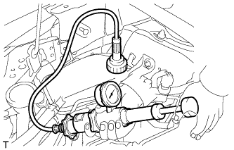
Fill the radiator with engine coolant, and then attach a radiator cap tester.
-
Warm up the engine.
-
Using the radiator cap tester, increase the pressure inside the radiator to 118 kPa (1.2 kgf/cm2, 17 psi), and then check that the pressure does not drop.
If the pressure drops, check the hoses, radiator and water pump for leakage. If there are no signs or traces of external engine coolant leakage, check the heater core, cylinder block and head.
-
-
INSTALL RADIATOR SUPPORT OPENING COVER
-
Attach the 4 hooks to install the radiator support opening cover.
-
Install the 3 clips.
-