REAR CRANKSHAFT OIL SEAL INSTALLATION

-
INSTALL REAR CRANKSHAFT OIL SEAL
-
Apply MP grease to the lip of a new rear crankshaft oil seal.
-
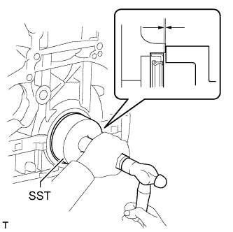
Using SST and a hammer, tap in the rear crankshaft oil seal as shown in the illustration.
- SST
- 09223-56010
Standard depth 0 to 0.9 mm (0 to 0.0354 in.) Note
-
Keep the lip free from foreign matter.
-
Do not tap the rear crankshaft oil seal at an angle.
-
Make sure that the rear crankshaft oil seal is properly installed.
-
-
INSTALL FLYWHEEL SUB-ASSEMBLY (for Manual Transaxle)
-
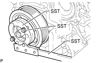
Using SST, hold the crankshaft pulley.
- SST
- 09213-58014 ( 91551-80840 )
- 09330-00021
-
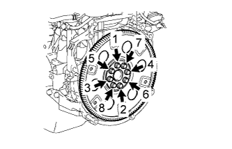
Using a T55 "TORX" socket wrench, install the flywheel sub-assembly with 8 new bolts and uniformly tighten the bolts in several steps in the sequence shown in the illustration.
- Torque:
- 71 N*m { 720 kgf*cm, 52 ft.*lbf }
Note
-
Do not reuse the flywheel installation bolts.
-
Be sure to check the tightening torque within 5 minutes after tightening.
-
Do not impact or damage the flywheel installation bolts. Be sure to handle them carefully.
-
Make sure there is no oil on the bolts.
Tech Tips
Make sure that the seating surface of the flywheel installation bolts and installation surfaces of the crankshaft and flywheel sub-assembly are free from oil and foreign matter.
-
-
INSTALL DRIVE PLATE AND RING GEAR SUB-ASSEMBLY (for Automatic Transaxle)
-
Using SST hold the crankshaft pulley.
- SST
- 09213-58014 ( 91551-80840 )
- 09330-00021
-
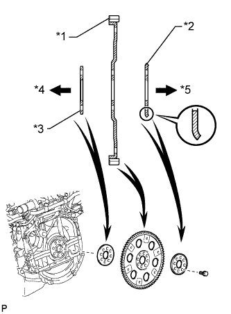
Text in Illustration *1 Drive Plate and Ring Gear Sub-assembly *2 Rear Drive Plate Spacer *3 Front Drive Plate Spacer
(Reversible)
*4 Engine Side *5 Transaxle Side Install the front drive plate spacer, drive plate and ring gear sub-assembly, and rear drive plate spacer to the crankshaft.
Tech Tips
-
The front drive plate spacer is reversible.
-
As the rear drive plate spacer and drive plate and ring gear sub-assembly are not reversible, be sure to install them in the direction shown in the illustration.
-
-
Apply adhesive to 2 or 3 threads at the end of each bolt.
Adhesive Toyota Genuine Adhesive 1324, Three Bond 1324 or equivalent -
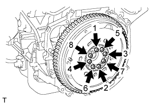
Uniformly install and tighten the 8 bolts in several steps in the sequence shown in the illustration.
- Torque:
- 92 N*m { 938 kgf*cm, 68 ft.*lbf }
-
-
INSTALL CLUTCH DISC ASSEMBLY (for Manual Transaxle)
-
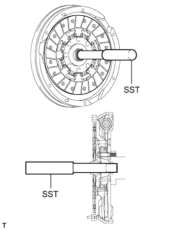
Insert SST into the clutch disc, and then insert them into the flywheel.
- SST
- 09301-00310
Note
Insert the clutch disc with the disc facing in the correct direction.
-
-
INSTALL CLUTCH COVER ASSEMBLY (for Manual Transaxle)
-
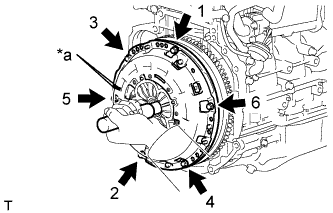
Text in Illustration *a Matchmark Align the matchmark on the clutch cover with the one on the flywheel.
-
Install and tighten the 6 bolts uniformly in the order shown in the illustration, starting with the bolt located near the knock pin on the top.
- Torque:
- 19 N*m { 195 kgf*cm, 14 ft.*lbf }
Note
-
Be sure to uniformly tighten the bolts 180° at a time according to the order in the illustration.
-
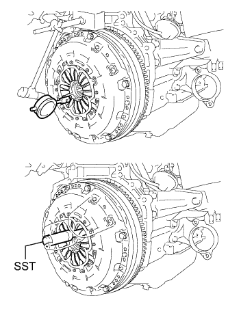
Move SST up and down, right and left lightly after checking that the clutch disc assembly is in the center, and then tighten the bolts.
-
-
INSPECT AND ADJUST CLUTCH COVER ASSEMBLY (for Manual Transaxle)
-
Using a dial indicator with a roller instrument, measure the diaphragm spring tip alignment.
Maximum misalignment 1.3 mm (0.0512 in.) If the misalignment is more than the maximum, using SST, adjust the diaphragm spring tip alignment.
- SST
- 09333-00013
-
-
INSTALL MANUAL TRANSAXLE ASSEMBLY (for Manual Transaxle)
-
INSTALL AUTOMATIC TRANSAXLE ASSEMBLY
-
CONNECT CABLE TO NEGATIVE BATTERY TERMINAL
Note
When disconnecting the cable, some systems need to be initialized after the cable is reconnected Click here.