AUDIO AND VISUAL SYSTEM (for Radio Receiver Type) AVC-LAN Circuit
DESCRIPTION
Each unit of the audio system connected to the AVC-LAN (communication bus) transfers the signal of each switch by communication.
When a short to +B or a short to ground occurs in the AVC-LAN, the audio system will not function normally as communication is discontinued.
WIRING DIAGRAM
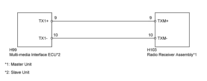
INSPECTION PROCEDURE
PROCEDURE
-
INSPECT RADIO RECEIVER ASSEMBLY
-
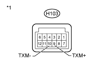
Text in Illustration *1 Component without harness connected
(Radio Receiver Assembly)
Disconnect the H103 radio receiver assembly connector.
-
Measure the resistance according to the value(s) in the table below.
Standard Resistance Tester Connection Condition Specified Condition H103-9 (TXM+) - H103-10 (TXM-) Always 60 to 80 Ω
NG 
REPLACE RADIO RECEIVER ASSEMBLY Click here
OK 
-
-
CHECK HARNESS AND CONNECTOR (RADIO RECEIVER - COMPONENT WHICH HAS STORED THIS CODE)
Tech Tips
For details of the connectors, refer to Terminals of ECU Click here.
-
Referring to the wiring diagram, check the AVC-LAN circuit between the radio receiver assembly and the component which has stored this code.
-
Disconnect all connectors between the radio receiver assembly and the component which has stored this code.
-
Check for an open or short in the AVC-LAN circuit between the radio receiver assembly and the component which has stored this code.
OK There is no open or short circuit.
-
NG
REPAIR OR REPLACE HARNESS OR CONNECTOR
OK 
PROCEED TO NEXT SUSPECTED AREA SHOWN IN PROBLEM SYMPTOMS TABLE Click here
-