PARKING BRAKE CABLE INSTALLATION

-
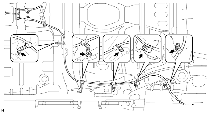
INSTALL NO. 3 PARKING BRAKE CABLE ASSEMBLY
-
Install the No. 3 parking brake cable with the 4 bolts.
- Torque:
- 6.0 N*m { 61 kgf*cm, 53 in.*lbf }
-
Attach the clamp.
-
Install the casing cap with the bolt.
- Torque:
- 6.0 N*m { 61 kgf*cm, 53 in.*lbf }
-
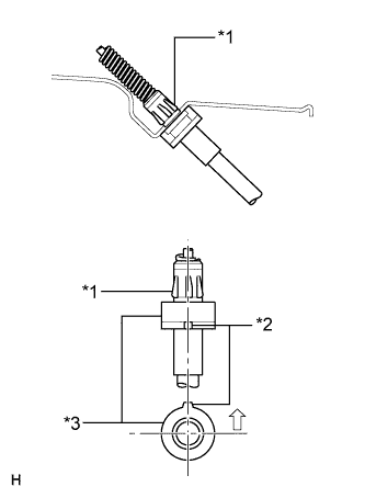
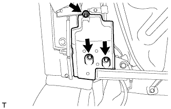
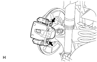
Text in Illustration *1 Spring Clip *2 Projection *3 Casing Cap Attach the spring clip of the No. 3 parking brake cable to the backing plate, as shown in the illustration.
Note
-
Make sure the spring clip passes completely through the hole of the backing plate.
-
Make sure the projection of the casing cap faces upward.
-
-
-
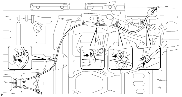
INSTALL NO. 2 PARKING BRAKE CABLE ASSEMBLY
-
Install the No. 2 parking brake cable with the 5 bolts.
- Torque:
- 6.0 N*m { 61 kgf*cm, 53 in.*lbf }
-
Attach the clamp.
-
Install the casing cap with the bolt.
- Torque:
- 6.0 N*m { 61 kgf*cm, 53 in.*lbf }
-
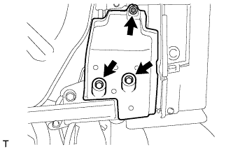
Text in Illustration *1 Spring Clip *2 Projection *3 Casing Cap Attach the spring clip of the No. 2 parking brake cable to the backing plate, as shown in the illustration.
Note
-
Make sure the spring clip passes completely through the hole of the backing plate.
-
Make sure the projection of the casing cap faces upward.
-
-
-
INSTALL NO. 2 FRONT FLOOR HEAT INSULATOR
-
Install the No. 2 front floor heat insulator with the 3 nuts.
- Torque:
- 5.5 N*m { 56 kgf*cm, 49 in.*lbf }
-
-
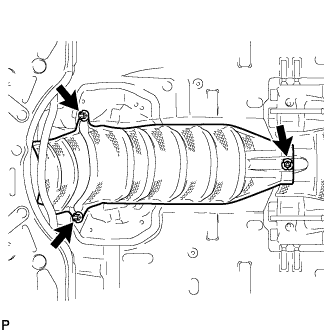
INSTALL FRONT EXHAUST PIPE ASSEMBLY
-
for 1ZR-FAE:
Install the front exhaust pipe assembly Click here.
-
for 2ZR-FAE:
Install the front exhaust pipe assembly Click here.
-
for 1AD-FTV:
Install the front exhaust pipe assembly Click here.
-
for 2AD-FHV:
Install the front exhaust pipe assembly Click here.
-
-
INSTALL REAR FLOOR SIDE MEMBER COVER LH (for 1ZR-FAE)
-
Install the rear floor side member cover with the nut and 2 bolts.
-
-
INSTALL REAR FLOOR SIDE MEMBER COVER LH (for 2ZR-FAE)
-
Install the rear floor side member cover with the nut and 2 bolts.
-
-
INSTALL REAR FLOOR SIDE MEMBER COVER LH (for 1AD-FTV)
-
Install the rear floor side member cover with the nut and 2 bolts.
-
-
INSTALL REAR FLOOR SIDE MEMBER COVER LH (for 2AD-FHV)
-
Install the rear floor side member cover with the nut and 2 bolts.
-
-
INSTALL REAR FLOOR SIDE MEMBER COVER RH (for 1ZR-FAE)
-
Install the rear floor side member cover with the nut and 2 bolts.
-
-
INSTALL REAR FLOOR SIDE MEMBER COVER RH (for 2ZR-FAE)
-
Install the rear floor side member cover with the nut and 2 bolts.
-
-
INSTALL REAR FLOOR SIDE MEMBER COVER RH (for 1AD-FTV)
-
Install the rear floor side member cover with the nut and 2 bolts.
-
-
INSTALL REAR FLOOR SIDE MEMBER COVER RH (for 2AD-FHV)
-
Install the rear floor side member cover with the nut and 2 bolts.
-
-
CONNECT NO. 3 PARKING BRAKE CABLE ASSEMBLY
-
Connect the No. 3 parking brake cable Click here.
-
-
CONNECT NO. 2 PARKING BRAKE CABLE ASSEMBLY
Tech Tips
Use the same procedure described for the No. 3 parking brake cable.
-
CONNECT REAR DISC BRAKE CYLINDER ASSEMBLY LH
-
Connect the rear disc brake cylinder with the 2 bolts.
- Torque:
- 57 N*m { 585 kgf*cm, 42 ft.*lbf }
Note
-
Do not twist the brake hose.
-
Make sure that the bolts are free from damage and foreign matter.
-
-
CONNECT REAR DISC BRAKE CYLINDER ASSEMBLY RH
Tech Tips
Use the same procedure described for the LH side.
-
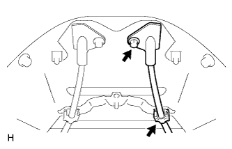
CONNECT PARKING BRAKE CABLE
-
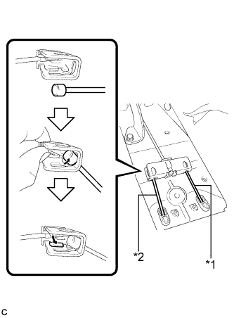
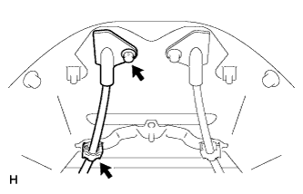
Text in Illustration *1 No. 2 Parking Brake Cable *2 No. 3 Parking Brake Cable Connect the No. 3 parking brake cable to the parking brake equalizer as shown in the illustration.
-
Connect the No. 2 parking brake cable to the parking brake equalizer.
Tech Tips
Use the same procedure described for the No. 3 parking brake cable.
-
-
INSTALL NO. 2 CONSOLE BOX MOUNTING BRACKET
-
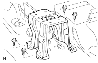
Install the No. 2 console box mounting bracket with the 4 bolts.
- Torque:
- 27 N*m { 275 kgf*cm, 19 ft.*lbf }
-
Install the floor carpet.
-
-
CHECK PARKING BRAKE LEVER TRAVEL
-
Pull the parking brake lever to fully engage the parking brake.
-
Release the lever to disengage the parking brake.
-
Slowly pull the parking brake lever all the way, and count the number of clicks.
Standard parking brake lever travel when pulled with a force of 200 N (20 kgf, 45 lbf) 6 to 9 clicks
-
-
ADJUST PARKING BRAKE LEVER TRAVEL
-
Remove the console box assembly Click here.
-
Completely release the parking brake lever.
-
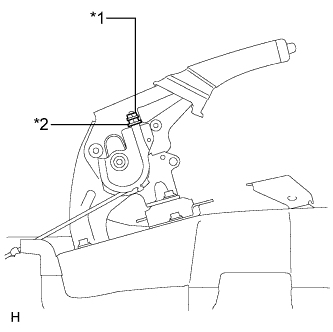
Text in Illustration *1 Lock Nut *2 Adjusting Nut Loosen the lock nut and adjusting nut to completely release the parking brake cable.
-
Temporarily install the hub nuts.
-
Remove the shoe adjusting hole plug.
-
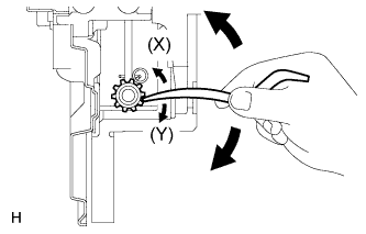
Insert an adjustment tool into the adjustment hole of the disc. Rotate the adjustment wheel in the "X" direction until the shoes are locked. Then rotate the adjustment wheel in the "Y" direction 8 notches.
-
Check that the disc can be rotated lightly. If not, rotate the adjustment wheel in the "Y" direction and check again.
-
Install the hole plug.
-
Remove the hub nuts.
-
Turn the adjusting nut until the parking brake lever travel becomes correct.
Standard parking brake lever travel when pulled with a force of 200 N (20 kgf, 45 lbf) 6 to 9 clicks -
Using a wrench or equivalent, hold the adjusting nut and tighten the lock nut.
- Torque:
- 6.0 N*m { 61 kgf*cm, 53 in.*lbf }
-
Operate the parking brake lever 3 to 4 times, and check the parking brake lever travel.
Standard parking brake lever travel when pulled with a force of 200 N (20 kgf, 45 lbf) 6 to 9 clicks -
Check whether the parking brake drags or not.
-
Operate the parking brake lever and check the illumination condition of the brake warning light.
OK The brake warning light always illuminates at the first click. -
Install the console box assembly Click here.
-
-
INSTALL CONSOLE BOX ASSEMBLY
-
Install the console box assembly Click here.
-
-
INSTALL FRONT SEAT ASSEMBLY LH
-
Install the front seat assembly LH Click here.
-
-
INSTALL FRONT SEAT ASSEMBLY RH
Tech Tips
Use the same procedure described for the LH side.
-
CONNECT CABLE TO NEGATIVE BATTERY TERMINAL
Note
When disconnecting the cable, some systems need to be initialized after the cable is reconnected Click here.
-
CHECK SRS WARNING LIGHT
-
Check the SRS warning light Click here.
-
-
INSPECT FOR EXHAUST GAS LEAK
-
INSTALL REAR WHEEL
- Torque:
- 103 N*m { 1050 kgf*cm, 76 ft.*lbf }