- Click here
INSTALL ECM
-
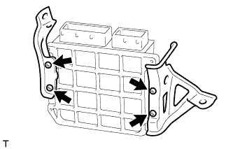
Install the 2 brackets to the ECM with the 4 screws.
3.0 N*m 31 kgf*cm 27 in.*lbf -
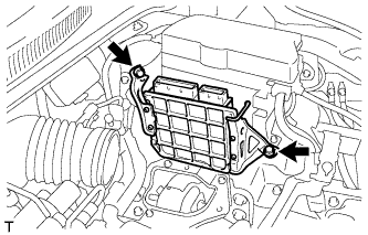
Install the ECM with bracket with the 2 bolts.
8.0 N*m 82 kgf*cm 71 in.*lbf -
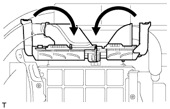
Connect the 2 ECM connectors and lower the 2 levers.
Note:
-
When connecting the connector, make sure that dirt, water or other foreign matter is not stuck between the connector and ECM.
-
Make sure that the 2 levers are securely lowered.
-
-
- Click here
INSTALL NO. 2 AIR CLEANER INLET
-
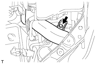
Install the No. 2 air cleaner inlet with the bolt.
7.0 N*m 71 kgf*cm 62 in.*lbf
-
- Click here
INSTALL NO. 1 AIR CLEANER INLET
-
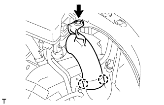
Attach the 2 claws to install the No. 1 air cleaner inlet.
-
Install the clip.
-
- Click here
INSTALL AIR CLEANER CASE SUB-ASSEMBLY
-
Install the air cleaner case with the 3 bolts.
7.0 N*m 71 kgf*cm 62 in.*lbf
-
- Click here
INSTALL AIR CLEANER FILTER ELEMENT SUB-ASSEMBLY
- Click here
INSTALL AIR CLEANER CAP SUB-ASSEMBLY
-
Connect the air cleaner hose assembly to the turbocharger sub-assembly, and slide the clamp secure it.
-
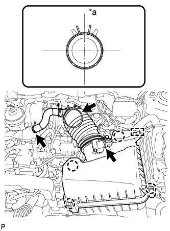
Attach the 4 clamps to install the air cleaner cap sub-assembly.
Table 1. Text in Illustration *a Upper -
Connect the PCV hose to the cylinder head cover sub-assembly, and slide the clamp secure it.
-
Attach the clamp and connect the mass air flow meter connector.
-
- Click here
INSTALL RADIATOR SUPPORT OPENING COVER
-
Attach the 4 hooks to install the radiator support opening cover.
-
Install the 3 clips.
-
- Click here
INSTALL NO. 1 ENGINE COVER
-
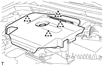
Attach the 4 clips to install the No. 1 engine cover.
-
- Click here
CONNECT CABLE TO NEGATIVE BATTERY TERMINAL
Note:When disconnecting the cable, some systems need to be initialized after the cable is reconnected (Click here).
- Click here
PERFORM REGISTRATION
-
for CCo: (Click here)
-
for DPF: (Click here)
-
- Click here
PERFORM INITIALIZATION
-
for CCo: (Click here)
-
for DPF: (Click here)
-
- Click here
PERFORM THROTTLE VALVE FULLY CLOSED POSITION LEARNING
Tip:Be sure to turn off the ignition switch before performing this inspection.
-
Turn the ignition switch to ON.
-
Turn the ignition switch off and wait 10 seconds.
Tip:The fully closed position of the diesel throttle valve is learned when the ignition switch is turned off.
-