ECD SYSTEM (for CCo), Diagnostic DTC:P0101

| DTC Code | DTC Name |
|---|---|
| P0101 | Mass or Volume Air Flow Circuit Range / Performance Problem |
DESCRIPTION
Refer to DTC P0102 Click here.
| DTC Detection Drive Pattern | DTC Detection Condition | Trouble Area |
|---|---|---|
| After the engine is completely warmed up, perform the following procedure 3 times: from a vehicle speed of 60 km/h (37 mph), accelerate the vehicle to 80 km/h (50 mph), quickly release the accelerator pedal and do not depress it for 7 seconds or more. | After the engine is completely warmed up, while the accelerator pedal is released for 7 seconds or more and the vehicle is decelerating, the intake air volume is higher or lower than the threshold*1 (EGR valve fully closed and throttle valve is fully open). (2 trip detection logic) |
Mass air flow meter IAT sensor Manifold absolute pressure sensor EGR valve ECM Open or short in Mass Air Flow (MAF) meter circuit |
*1: There is a threshold for a low air flow rate malfunction and high air flow rate malfunction. The threshold is different depending on the values of "Engine Speed", "MAP" and "Intake Air Temp (Turbo)".
Tech Tips
-
Low air flow rate malfunction: For example when vehicle deceleration if "MAF" is 28 g/s or less, low air flow malfunction is confirmed (at "Engine Speed" is 1600 rpm, "MAP" is 110 kPa and "Intake Air Temp (Turbo)" is 35°C).
-
High air flow rate malfunction: For example when vehicle deceleration if "MAF" is 42 g/s or more, high air flow malfunction is confirmed (at "Engine Speed" is 1600 rpm, "MAP" is 110 kPa and "Intake Air Temp (Turbo)" is 35°C).
| DTC No. | Data List |
|---|---|
| P0101 |
|
Tech Tips
If DTC P0101 is stored, either of the following symptoms may appear:
-
As the ECU mistakenly determines that there is less air than the actual intake air amount, EGR is decreased to match the target EGR.
-
Combustion noise worsens
-
As the ECU mistakenly determines that there is more air than the actual intake air amount, EGR is increased to match the target EGR:
-
Misfire
-
White smoke
-
Black smoke
INSPECTION PROCEDURE
Note
After replacing the ECM, the new ECM needs registration Click here and initialization Click here.
Tech Tips
Read freeze frame data using the intelligent tester. Freeze frame data records the engine condition when malfunctions are detected. When troubleshooting, freeze frame data can help determine if the vehicle was moving or stationary, if the engine was warmed up or not, and other data from the time the malfunction occurred.
PROCEDURE
-
CHECK OTHER DTC OUTPUT (IN ADDITION TO DTC P0101)
-
Connect the intelligent tester to the DLC3.
-
Turn the ignition switch to ON and turn the tester on.
-
Enter the following menus: Powertrain / Engine and ECT / DTC.
-
Read the DTCs.
Result Result Proceed to P0101 and other DTCs are output A P0101 is output B Tech Tips
If codes other than P0101 are output, perform troubleshooting for those DTCs first.
A 
GO TO DTC CHART Click here
B 
-
-
CHECK FREEZE FRAME DATA (MASS AIR FLOW RATE AND ENGINE SPEED)
-
Connect the intelligent tester to the DLC3.
-
Turn the ignition switch to ON.
-
Turn the tester on.
-
Enter the following menus: Powertrain / Engine and ECT / DTC.
-
Check the freeze frame data.
Result Result Proceed to Engine speed 1250 rpm or less
MAF 180.0 g/s or more
A Engine speed 1250 rpm or more
MAF 0.03 g/s or less
Except above B
B 
READ VALUE USING INTELLIGENT TESTER (MASS AIR FLOW RATE AND ENGINE SPEED) Click here
A
-
-
READ VALUE USING INTELLIGENT TESTER (MASS AIR FLOW RATE AND ENGINE SPEED)
-
Connect the intelligent tester to the DLC3.
-
Start the engine and turn the tester on.
-
Enter the following menus: Powertrain / Engine and ECT / Data List / MAF and Engine speed.
-
Read the value.
Standard Engine speed MAF 0 rpm 0.03 g/s or less 720 to 820 rpm 100 g/s or less 3000 rpm 1 g/s or more
NG
CHECK HARNESS AND CONNECTOR (MASS AIR FLOW METER - ECM) Click here
OK
-
-
REPLACE MASS AIR FLOW METER
-
Replace the mass air flow meter Click here.
NEXT
-
-
CHECK DTC OUTPUT
-
Connect the intelligent tester to the DLC3.
-
Clear the DTCs Click here.
-
Turn the ignition switch off for 30 seconds or more.
-
Start the engine.
-
After the engine is completely warmed up, perform the following procedure 3 times with the A/C off: from a vehicle speed of 60 km/h (37 mph), accelerate the vehicle to 80 km/h (50 mph), quickly release the accelerator pedal and do not depress it for 7 seconds or more.
-
Stop the vehicle immediately after completing the above procedure.
-
Connect the intelligent tester to the DLC3.
-
Enter the following menus: Powertrain / Engine and ECT / DTC.
-
Read the pending DTCs.
Tech Tips
-
If no pending DTCs are output, proceed to the next step to check "All Readiness".
-
Perform the following procedure using the tester to determine whether or not the DTC judgment has been carried out.
-
Enter the following menus: Powertrain / Engine and ECT / Utility / All Readiness.
-
Input DTC P0101.
-
Check the DTC judgment result.
Result Tester Display Result Proceed to Pending DTC P0101 is output B All Readiness NORMAL A ABNORMAL B Tech Tips
If STATUS is INCOMPLETE or UNKNOWN, perform the following procedure again 3 times with the A/C off: from a vehicle speed of 60 km/h (37 mph), accelerate the vehicle to 80 km/h (50 mph), quickly release the accelerator pedal and do not depress it for 7 seconds or more.
-
A
END
B
-
-
CHECK HARNESS AND CONNECTOR (MASS AIR FLOW METER - ECM)
-
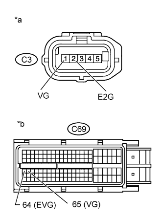
Text in Illustration *a Front view of wire harness connector
(to Mass Air Flow Meter)
*b Front view of wire harness connector
(to ECM)
Disconnect the mass air flow meter connector.
-
Disconnect the ECM connector.
-
Measure the resistance according to the value(s) in the table below.
Standard Resistance (Check for Open) Tester Connection Condition Specified Condition C3-1 (VG) - C69-65 (VG) Always Below 1 Ω C3-2 (E2G) - C69-64 (EVG) Always Below 1 Ω Standard Resistance (Check for Short) Tester Connection Condition Specified Condition C3-1 (VG) or C69-65 (VG) - Body ground Always 10 kΩ or higher -
Reconnect the mass air flow meter connector.
-
Reconnect the ECM connector.
NG
REPAIR OR REPLACE HARNESS OR CONNECTOR Click here
OK
-
-
REPLACE ECM
-
Replace the ECM Click here.
NEXT
CONFIRM WHETHER MALFUNCTION HAS BEEN SUCCESSFULLY REPAIRED Click here
-
-
READ VALUE USING INTELLIGENT TESTER (MASS AIR FLOW RATE AND ENGINE SPEED)
-
Connect the intelligent tester to the DLC3.
-
Turn the ignition switch to ON and turn the tester on.
-
Enter the following menus: Powertrain / Engine and ECT / Data List / MAF and Engine speed.
-
Read the value.
Standard Engine speed MAF 0 rpm 0.03 g/s or less
NG
CHECK HARNESS AND CONNECTOR (MASS AIR FLOW METER - ECM) Click here
OK
-
-
READ VALUE USING INTELLIGENT TESTER (MAP AND ATMOSPHERIC PRESSURE)
-
Connect the intelligent tester to the DLC3.
-
Turn the ignition switch to ON and turn the tester on.
-
Enter the following menus: Powertrain / Engine and ECT / Data List / MAP and Atmospheric Pressure.
-
Compare the values when the ignition switch is ON.
Standard Difference between MAP and Atmosphere Pressure is less than 8 kPa. Tech Tips
-
If MAP and Atmosphere Pressure have the same value, both are normal. If there is a difference of 8 kPa or more, compare the values to the atmospheric pressure for that day. The sensor whose deviation is the greatest is malfunctioning.
-
Standard atmospheric pressure is 101 kPa. For every 100 m increase in altitude, pressure drops by 1 kPa. Varies by weather.
-
NG
REPLACE MANIFOLD ABSOLUTE PRESSURE SENSOR Click here
OK
-
-
INSPECT INTAKE AIR TEMPERATURE SENSOR
-
Inspect the intake air temperature sensor Click here.
NG
REPLACE INTAKE AIR TEMPERATURE SENSOR Click here
OK
-
-
INSPECT EGR VALVE ASSEMBLY
-
Connect the intelligent tester to the DLC3.
-
Turn the ignition switch to ON and turn the tester on.
-
Enter the following menus: Powertrain / Engine and ECT / Active Test / Control the EGR Step Position.
-
When changing the Active Test continuously value to 0, 30, 60, 90, 60, 30 and 0%, check that Actual EGR Valve Pos. smoothly changes to the set opening angle.
OK Value smoothly changes to set opening angle. -
Enter the following menus: Powertrain / Engine and ECT / Data List / EGR Close Lrn. Status.
-
Read the values.
Standard EGR Close Lrn. Status is OK -
Remove the EGR valve assembly Click here.
-
Visually check the electric EGR control valve for deposits.
If there are deposits, clean the electric EGR control valve.
Note
-
When cleaning the electric EGR control valve, make sure the valve is completely closed.
-
Do not forcibly open the valve, as it may be damaged or deformed.
-
When cleaning the electric EGR control valve, use a piece of cloth soaked with cleaning solvent. Spraying the solvent directly onto these parts or soaking the parts in the solvent may damage the parts.
-
-
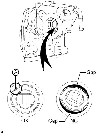
Hold the electric EGR control valve up to a light, and then from the side indicated by the arrow in the illustration, visually check that there is no gap between the valve and body.
OK No light passes through (there is no gap between the valve and body). If light passes through (there is a gap between the valve and body), replace the electric EGR control valve assembly.
Tech Tips
Light passes through part A shown in the illustration even if the valve is completely closed, this is not a problem.
NG
REPLACE EGR VALVE ASSEMBLY Click here
OK
-
-
CHECK AIR INDUCTION SYSTEM
-
Check the air induction system for vacuum leakage Click here.
OK No leakage from air induction system. Tech Tips
-
Check for abnormal disconnection, pipe and hose squashing, and any damage in the intake system.
-
Using your hand, check whether the pipes and hoses in the intake system are securely connected.
-
Air leaks from the intake system can be checked by applying soapy water and revving the engine.
-
Check for any modifications in the intake system made by the user.
-
NG
REPAIR OR REPLACE AIR INDUCTION SYSTEM Click here
OK
-
-
CHECK HARNESS AND CONNECTOR (MASS AIR FLOW METER - ECM)
-
Text in Illustration *a Front view of wire harness connector
(to Mass Air Flow Meter)
*b Front view of wire harness connector
(to ECM)
Disconnect the mass air flow meter connector.
-
Disconnect the ECM connector.
-
Measure the resistance according to the value(s) in the table below.
Standard Resistance (Check for Open) Tester Connection Condition Specified Condition C3-1 (VG) - C69-65 (VG) Always Below 1 Ω C3-2 (E2G) - C69-64 (EVG) Always Below 1 Ω Standard Resistance (Check for Short) Tester Connection Condition Specified Condition C3-1 (VG) or C69-65 (VG) - Body ground Always 10 kΩ or higher -
Reconnect the mass air flow meter connector.
-
Reconnect the ECM connector.
NG
REPAIR OR REPLACE HARNESS OR CONNECTOR Click here
OK
-
-
REPLACE MASS AIR FLOW METER
-
Replace the mass air flow meter Click here.
NEXT
-
-
CHECK DTC OUTPUT
-
Connect the intelligent tester to the DLC3.
-
Clear the DTCs Click here.
-
Turn the ignition switch off for 30 seconds or more.
-
Start the engine.
-
After the engine is completely warmed up, perform the following procedure 3 times with the A/C off: from a vehicle speed of 60 km/h (37 mph), accelerate the vehicle to 80 km/h (50 mph), quickly release the accelerator pedal and do not depress it for 7 seconds or more.
-
Stop the vehicle immediately after completing the above procedure.
-
Connect the intelligent tester to the DLC3.
-
Enter the following menus: Powertrain / Engine and ECT / DTC.
-
Read the pending DTCs.
Tech Tips
-
If no pending DTCs are output, proceed to the next step to check "All Readiness".
-
Perform the following procedure using the tester to determine whether or not the DTC judgment has been carried out.
-
Enter the following menus: Powertrain / Engine and ECT / Utility / All Readiness.
-
Input DTC P0101.
-
Check the DTC judgment result.
Result Tester Display Result Proceed to Pending DTC P0101 is output B All Readiness NORMAL A ABNORMAL B Tech Tips
If STATUS is INCOMPLETE or UNKNOWN, perform the following procedure again 3 times with the A/C off: from a vehicle speed of 60 km/h (37 mph), accelerate the vehicle to 80 km/h (50 mph), quickly release the accelerator pedal and do not depress it for 7 seconds or more.
-
B
REPLACE ECM Click here
A 
END
-
-
REPAIR OR REPLACE AIR INDUCTION SYSTEM
-
Repair or replace the air induction system.
NEXT
CONFIRM WHETHER MALFUNCTION HAS BEEN SUCCESSFULLY REPAIRED Click here
-
-
REPLACE EGR VALVE ASSEMBLY
-
Replace the EGR valve assembly Click here.
NEXT
CONFIRM WHETHER MALFUNCTION HAS BEEN SUCCESSFULLY REPAIRED Click here
-
-
REPLACE ECM
-
Replace the ECM Click here.
NEXT
CONFIRM WHETHER MALFUNCTION HAS BEEN SUCCESSFULLY REPAIRED Click here
-
-
REPLACE MANIFOLD ABSOLUTE PRESSURE SENSOR
-
Replace the manifold absolute pressure sensor Click here.
NEXT
CONFIRM WHETHER MALFUNCTION HAS BEEN SUCCESSFULLY REPAIRED Click here
-
-
REPLACE INTAKE AIR TEMPERATURE SENSOR
-
Replace the intake air temperature sensor Click here.
NEXT
CONFIRM WHETHER MALFUNCTION HAS BEEN SUCCESSFULLY REPAIRED Click here
-
-
REPAIR OR REPLACE HARNESS OR CONNECTOR
-
Repair or replace the harness or connector.
NEXT
-
-
CONFIRM WHETHER MALFUNCTION HAS BEEN SUCCESSFULLY REPAIRED
-
Connect the intelligent tester to the DLC3.
-
Clear the DTCs Click here.
-
Turn the ignition switch off for 30 seconds or more.
-
Start the engine.
-
After the engine is completely warmed up, perform the following procedure 3 times with the A/C off: from a vehicle speed of 60 km/h (37 mph), accelerate the vehicle to 80 km/h (50 mph), quickly release the accelerator pedal and do not depress it for 7 seconds or more.
-
Stop the vehicle immediately after completing the above procedure.
-
Connect the intelligent tester to the DLC3.
-
Enter the following menus: Powertrain / Engine and ECT / DTC.
-
Confirm that the pending DTC is not output again.
Tech Tips
Perform the following procedure using the tester to determine whether or not the DTC judgment has been carried out.
-
Enter the following menus: Powertrain / Engine and ECT / Utility / All Readiness.
-
Input DTC P0101.
-
Check the DTC judgment result.
Tech Tips
If STATUS is INCOMPLETE or UNKNOWN, perform the following procedure again 3 times with the A/C off: from a vehicle speed of 60 km/h (37 mph), accelerate the vehicle to 80 km/h (50 mph), quickly release the accelerator pedal and do not depress it for 7 seconds or more.
-
NEXT
END
-