ECD SYSTEM (for CCo), Diagnostic DTC:P0088

| DTC Code | DTC Name |
|---|---|
| P0088 | Fuel Rail / System Pressure - Too High |
DESCRIPTION
| DTC Detection Drive Pattern | DTC Detection Condition | Trouble Area |
|---|---|---|
| After idling for 60 seconds, repeat quick engine speed accelerations (to 2500 rpm) for 30 seconds | The fuel pressure of the common rail exceeds 220000 kPa (2243 kgf/cm2, 319000 psi). (1 trip detection logic) |
|
| DTC No. | Data List |
|---|---|
| P0088 |
|
Tech Tips
-
For more information on the fuel supply pump (suction control valve) and common rail system, refer to System Description Click here.
-
When DTC P0088 is stored, check the internal fuel pressure of the common rail by entering the following menus: Powertrain / Engine and ECT / Data List / Fuel Press.
Reference Engine Speed Fuel Press Idling Approximately 27000 to 45000 kPa 3000 rpm (No engine load) Approximately 44000 to 78000 kPa -
When there is an operating problem with the fuel supply pump (when Fuel Press is more than Target Common Rail Pressure due to a problem with the closing of the suction valve), the values of Injection Pressure Correction and Target Pump SCV Current decrease.
-
Check "Fuel Press", "Target Common Rail Pressure", "Target Pump SCV Current" and "Fuel Pressure Relief Valve" in the freeze frame data.
MONITOR DESCRIPTION
P0088 (Internal fuel pressure too high):The ECM stores this DTC if the fuel pressure inside the common rail is more than 220000 kPa (2243 kgf/cm2, 31900 psi). This DTC indicates that: 1) the suction control valve may be stuck open, or 2) there may be a short in the suction control valve circuit.
If this DTC is stored, the ECM enters fail-safe mode and limits the engine power. The fail-safe mode continues until the ignition switch is turned off.
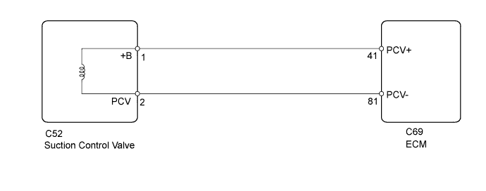
WIRING DIAGRAM
INSPECTION PROCEDURE
Note
-
After replacing the ECM, the new ECM needs registration Click here and initialization Click here.
-
After replacing the fuel supply pump, the ECM needs initialization Click here.
Tech Tips
Read freeze frame data using the intelligent tester. Freeze frame data records the engine condition when malfunctions are detected. When troubleshooting, freeze frame data can help determine if the vehicle was moving or stationary, if the engine was warmed up or not, and other data from the time the malfunction occurred.
PROCEDURE
-
READ VALUE USING INTELLIGENT TESTER (TARGET PUMP SCV CURRENT)
-
Connect the intelligent tester to the DLC3.
-
Start the engine.
-
Turn the tester on.
-
Enter the following menus: Powertrain / Engine and ECT / Data List / Target Pump SCV Current.
-
Read the value.
Standard Engine Speed Target Pump SCV Current Idling 923 to 1123 mA 2500 rpm (No engine load) 980 to 1212 mA
NG 
REPLACE SUCTION CONTROL VALVE Click here
OK 
-
-
READ VALUE USING INTELLIGENT TESTER (FUEL PRESS AND TARGET COMMON RAIL PRESSURE)
-
Connect the intelligent tester to the DLC3.
-
Start the engine.
-
Turn the tester on.
-
Enter the following menus: Powertrain / Engine and ECT / Data List / Fuel Press and Target Common Rail Pressure.
-
Check the difference in pressure between Fuel Press and Target Common Rail Pressure.
OK Difference in pressure between Fuel Press and Target Common Rail Pressure is within +/-5000 kPa.
NG
CHECK HARNESS AND CONNECTOR (SUCTION CONTROL VALVE CONNECTOR - ECM) Click here
OK
-
-
INSPECT PRESSURE DISCHARGE VALVE (COMMON RAIL)
-
Inspect the pressure discharge valve Click here.
OK
CONFIRM WHETHER MALFUNCTION HAS BEEN SUCCESSFULLY REPAIRED Click here
NG
REPLACE PRESSURE DISCHARGE VALVE (COMMON RAIL) Click here
-
-
REPLACE PRESSURE DISCHARGE VALVE (COMMON RAIL)
-
Replace the common rail Click here.
NEXT
BLEED AIR FROM FUEL SYSTEM Click here
-
-
CHECK HARNESS AND CONNECTOR (SUCTION CONTROL VALVE CONNECTOR - ECM)
-
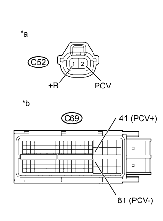
Text in Illustration *a Front view of wire harness connector
(to Suction Control Valve)
*b Front view of wire harness connector
(to ECM)
Disconnect the suction control valve connector.
-
Disconnect the ECM connector.
-
Measure the resistance according to the value(s) in the table below.
Standard Resistance (Check for Open) Tester Connection Condition Specified Condition C52-1 (+B) - C69-41 (PCV+) Always Below 1 Ω C52-2 (PCV) - C69-81 (PCV-) Always Below 1 Ω Standard Resistance (Check for Short) Tester Connection Condition Specified Condition C52-1 (+B) or C69-41 (PCV+) - Body ground Always 10 kΩ or higher C52-2 (PCV) or C69-81 (PCV-) - Body ground Always 10 kΩ or higher -
Reconnect the suction control valve connector.
-
Reconnect the ECM connector.
NG
REPAIR OR REPLACE HARNESS OR CONNECTOR Click here
OK
-
-
REPLACE SUCTION CONTROL VALVE
-
Replace the suction control valve Click here.
NEXT
-
-
BLEED AIR FROM FUEL SYSTEM
-
Bleed the air from the fuel system Click here.
NEXT
-
-
PERFORM FUEL SUPPLY PUMP INITIALIZATION
-
Perform fuel supply pump initialization Click here.
NEXT
-
-
CHECK DTC OUTPUT
-
Connect the intelligent tester to the DLC3.
-
Clear the DTCs Click here.
-
Turn the ignition switch off.
-
Start the engine.
-
After idling for 60 seconds, repeat engine speed accelerations (from idling to 2500 rpm) for 30 seconds.
-
Enter the following menus: Powertrain / Engine and ECT / DTC.
-
Read the DTCs.
Result Result Proceed to P0088 is output A No DTC is output B
B 
END
A
-
-
REPLACE ECM
-
Replace the ECM Click here.
NEXT
CONFIRM WHETHER MALFUNCTION HAS BEEN SUCCESSFULLY REPAIRED Click here
-
-
REPAIR OR REPLACE HARNESS OR CONNECTOR
-
Repair or replace the harness or connector.
NEXT
-
-
CONFIRM WHETHER MALFUNCTION HAS BEEN SUCCESSFULLY REPAIRED
-
Connect the intelligent tester to the DLC3.
-
Clear the DTCs Click here.
-
Turn the ignition switch off for 30 seconds or more.
-
Turn the ignition switch to ON and start the engine.
-
After idling for 60 seconds, repeat engine speed accelerations (from idling to 2500 rpm) for 30 seconds.
-
Confirm that the DTC is not output again.
Tech Tips
Perform the following procedure using the tester to determine whether or not the DTC judgment has been carried out.
-
Enter the following menus: Powertrain / Engine and ECT / Utility / All Readiness.
-
Input DTC P0088.
-
Check that STATUS is NORMAL. If STATUS is INCOMPLETE or UNKNOWN, race the engine to 2500 rpm repeatedly for 30 seconds and increase the idling time.
-
NEXT 
END
-