CONDENSER INSTALLATION

-
INSTALL COOLER CONDENSER ASSEMBLY
Tech Tips
A 2-bolt type radiator can be used in place of a 4-bolt type radiator.
-
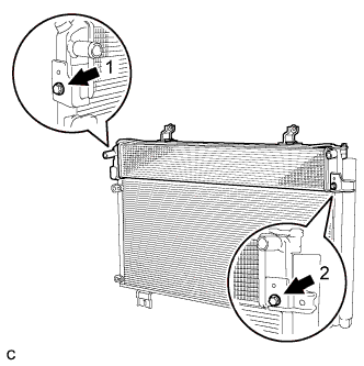
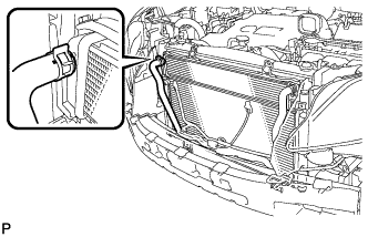
Radiator (2-bolt type):
-
Temporarily tighten the radiator assembly to the cooler condenser assembly with the 2 bolts.
-
Fully tighten the 2 bolts in the order shown in the illustration.
- Torque:
- 9.0 N*m { 92 kgf*cm, 80 in.*lbf }
-
-
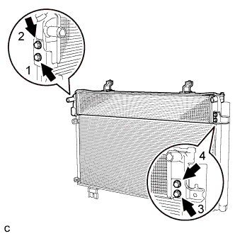
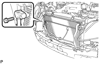
Radiator (4-bolt type):
-
Temporarily tighten the radiator assembly to the cooler condenser assembly with the 4 bolts.
-
Fully tighten the 4 bolts in the order shown in the illustration.
- Torque:
- 9.0 N*m { 92 kgf*cm, 80 in.*lbf }
-
-
Install the cooler condenser assembly with the 4 bolts.
Tech Tips
If the condenser is replaced with a new one, add compressor oil to the new condenser.
Capacity 40 cc (1.35 fl.oz.) Compressor oil ND-OIL 11 or equivalent - Torque:
- 6.0 N*m { 61 kgf*cm, 53 in.*lbf }
Note
Do not use any compressor oil other than ND-OIL 11 or equivalent. If any compressor oil other than ND-OIL 11 or equivalent is used, compressor motor insulation performance may decrease, resulting in a leakage of electric power.
-
-
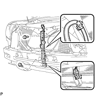
CONNECT OUTLET HYBRID RADIATOR HOSE
-
Using pliers, grip the claws of the clip and slide the clip to connect the outlet hybrid radiator hose.
-
-
CONNECT INLET HYBRID RADIATOR HOSE
-
Using pliers, grip the claws of the clip and slide the clip to connect the inlet hybrid radiator hose.
-
-
CONNECT DISCHARGE TUBE SUB-ASSEMBLY
-
Remove the attached vinyl tape from the tube and the connecting part of the cooler condenser assembly.
-
Sufficiently apply compressor oil to a new O-ring and the fitting surface of the tube joint.
Compressor oil ND-OIL 11 or equivalent -
Install the O-ring on the discharge tube sub-assembly.
Note
-
Keep the O-ring and O-ring fitting surfaces clean from dirt or any foreign objects.
-
Do not use any compressor oil other than ND-OIL 11 or equivalent. If any compressor oil other than ND-OIL 11 or equivalent is used, compressor motor insulation performance may decrease, resulting in a leakage of electric power.
-
-
Install the discharge tube sub-assembly on the cooler condenser assembly with the bolt.
- Torque:
- 5.4 N*m { 55 kgf*cm, 48 in.*lbf }
-
-
CONNECT AIR CONDITIONING TUBE AND ACCESSORY ASSEMBLY
-
Remove the attached vinyl tape from the pipe and the connecting part of the cooler condenser assembly.
-
Sufficiently apply compressor oil to a new O-ring and the fitting surface of the pipe joint.
Compressor oil ND-OIL 11 or equivalent -
Install the O-ring on the air conditioning tube and accessory assembly.
Note
-
Keep the O-ring and O-ring fitting surfaces clean from dirt or any foreign objects.
-
Do not use any compressor oil other than ND-OIL 11 or equivalent. If any compressor oil other than ND-OIL 11 or equivalent is used, compressor motor insulation performance may decrease, resulting in a leakage of electric power.
-
-
Install the air conditioning tube and accessory assembly on the cooler condenser assembly with the bolt.
- Torque:
- 5.4 N*m { 55 kgf*cm, 48 in.*lbf }
-
-
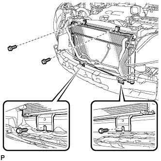
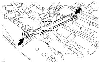
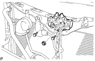
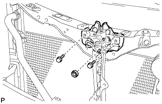
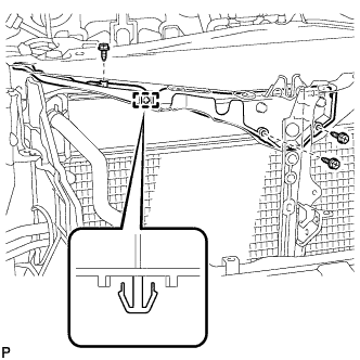
INSTALL UPPER RADIATOR SUPPORT
-
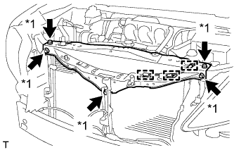
Text in Illustration *1 Bolt Install the upper radiator support with the 5 bolts and connect the 3 clamps of the hood lock control cable to the upper radiator support.
- Torque:
- 5.5 N*m { 56 kgf*cm, 49 in.*lbf }
-
-
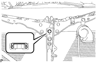
INSTALL HOOD LOCK SUPPORT SUB-ASSEMBLY
-
Install the hood lock support sub-assembly with the 2 bolts.
- Torque:
- 5.5 N*m { 56 kgf*cm, 49 in.*lbf }
-
Engage each clamp.
-
-
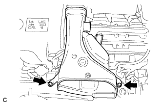
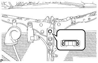
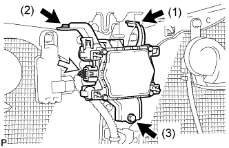
INSTALL NO. 3 INVERTER BRACKET
-
Install the No. 3 inverter bracket with the 2 bolts.
- Torque:
- 10 N*m { 102 kgf*cm, 7 ft.*lbf }
-
Install the hose clamp to the No. 3 inverter bracket.
-
-
INSTALL NO. 2 AIR CLEANER INLET
-
Install the inlet No. 2 air cleaner with the 2 bolts.
- Torque:
- 8.0 N*m { 82 kgf*cm, 71 in.*lbf }
-
-
INSTALL INTAKE AIR RESONATOR SUB-ASSEMBLY
-
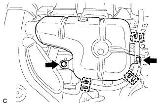
Install the intake air resonator sub-assembly to the inverter with converter assembly with the 2 bolts.
- Torque:
- 8.0 N*m { 82 kgf*cm, 71 in.*lbf }
-
Install the water hose with the 3 clamps to the intake air resonator sub-assembly.
-
-
INSTALL SMOG VENTILATION SENSOR (w/ Smog Ventilation Sensor)
-
Engage the guide.
-
Install the smog ventilation sensor with the bolt.
- Torque:
- 9.8 N*m { 100 kgf*cm, 87 in.*lbf }
-
Connect the connector.
-
-
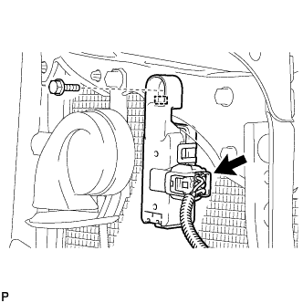
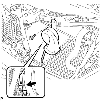
INSTALL HIGH PITCHED HORN ASSEMBLY
-
Install the high pitched horn assembly with the bolt.
- Torque:
- 19 N*m { 194 kgf*cm, 14 ft.*lbf }
-
Connect the connector.
-
-
INSTALL HOOD LOCK ASSEMBLY (for LHD)
-
Apply MP grease to the sliding areas of the lock.
-
Connect the hood lock control cable assembly.
-
Connect the connector.
-
Install the hood lock assembly with the 2 bolts and hood lock nut.
- Torque:
- 8.0 N*m { 82 kgf*cm, 71 in.*lbf }
-
Install a new hood lock nut cap.
-
-
INSTALL HOOD LOCK ASSEMBLY (for RHD)
-
Apply MP grease to the sliding areas of the lock.
-
Connect the hood lock control cable assembly.
-
Connect the connector.
-
Install the hood lock assembly with the 2 bolts and hood lock nut.
- Torque:
- 8.0 N*m { 82 kgf*cm, 71 in.*lbf }
-
Install a new hood lock nut cap.
-
-
INSTALL HOOD LOCK CONTROL CABLE COVER (for LHD)
-

Engage the clamp.
-
Install the hood lock control cable cover with the 3 screws.
-
-
INSTALL HOOD LOCK CONTROL CABLE COVER (for RHD)
-
Engage the clamp.
-
Install the hood lock control cable cover with the 3 screws.
-
-
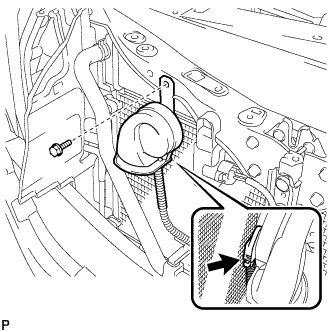
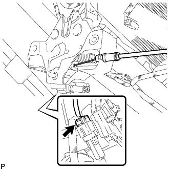
INSTALL LOW PITCHED HORN ASSEMBLY
-
Install the low pitched horn assembly with the bolt.
- Torque:
- 19 N*m { 194 kgf*cm, 14 ft.*lbf }
-
Connect the connector.
-
-
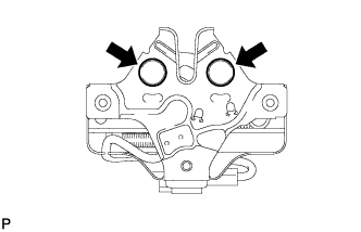
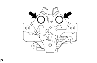
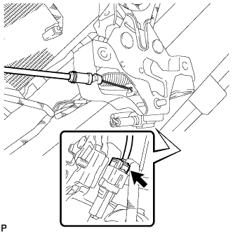
INSTALL MILLIMETER WAVE RADAR SENSOR ASSEMBLY (w/ Dynamic Radar Cruise Control System)
-
Tighten the 3 bolts on the millimeter wave radar sensor assembly.
- Torque:
- 5.5 N*m { 56 kgf*cm, 49 in.*lbf }
Tech Tips
Tighten the bolts in the order indicated in the illustration.
-
Connect the connector.
-
-
INSTALL FRONT BUMPER ASSEMBLY
for Standard: Click here
for Sport Package: Click here
-
CONNECT CABLE TO NEGATIVE AUXILIARY BATTERY TERMINAL
Note
When disconnecting the cable, some systems need to be initialized after the cable is reconnected Click here.
-
INSTALL REAR DECK FLOOR BOX
-
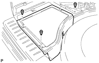
Install the rear deck floor box with the 3 clips.
-
-
CHARGE WITH REFRIGERANT
-
Perform vacuum purging using a vacuum pump.
-
Charge with refrigerant HFC-134a (R134a).
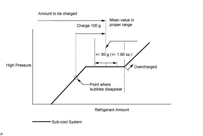
Standard 550 to 650 g (19.4 to 22.9 oz.) - SST
- 09985-20010 ( 09985-02010, 09985-02050, 09985-02060, 09985-02070, 09985-02080, 09985-02090, 09985-02110, 09985-02130, 09985-02140, 09985-02150 )
Note
-
Do not turn the A/C on before charging with refrigerant. Doing so will cause the compressor to work without refrigerant, resulting in overheating of the cooler compressor.
-
Approximately 100 g (3.53 oz.) of refrigerant may need to be charged after bubbles disappear. The refrigerant amount should be checked by quantity, not with the sight glass.
-
Avoid using the gauge manifold set that had been used for vehicles with conventional compressor oil (ND-OIL 8 or equivalent) as much as possible. This will cause compressor oil remaining in the manifold to enter the vehicle, resulting in insulation performance deterioration. A gauge manifold set that had been used 3 times or less can be reused if an appropriate one is not available.
Tech Tips
Ensure that sufficient refrigerant is available to recharge the system when using a refrigerant recovery unit. Refrigerant recovery units are not always able to recover 100% of the refrigerant from an A/C system.
-
-
ADD COOLANT (for Inverter)
Note
-
Do not reuse the drained coolant because it may contain foreign objects.
-
If the vehicle is driven with air in the inverter cooling system, the following DTCs may be set.
DTC Code Detection Item P0A01-726 Motor Electronics Coolant Temperature Sensor Circuit Range / Performance P0A04-725 Motor Electronics Coolant Temperature Sensor Circuit Intermittent P0A08-264 DC / DC Converter Status Circuit P0A78-284 Drive Motor "A" Inverter Performance P0A78-286 Drive Motor "A" Inverter Performance P0A79-692 Drive Motor "B" Inverter Performance P0A79-696 Drive Motor "B" Inverter Performance P0A7A-322 Generator Inverter Performance P0A7A-324 Generator Inverter Performance P0A93-346 Inverter Cooling System Performance P0A94-553 DC / DC Converter Performance P0A94-557 DC / DC Converter Performance P0AEE-277 Motor Inverter Temperature Sensor "A" Circuit Range / Performance P0AF1-276 Drive Motor Inverter Temperature Sensor "A" Circuit Intermittent / Erratic P0AF3-676 Sensor of Rear Motor Inverter Temperature P0AF6-675 Drive Motor Inverter Temperature Sensor "B" Circuit Intermittent / Erratic P0BCD-315 Generator Inverter Temperature Sensor Circuit Range / Performance P0BD0-314 Generator Inverter Temperature Sensor Circuit Intermittent / Erratic P0C39-626 DC / DC Converter Temperature Sensor "A" Range / Performance P0C3C-625 DC / DC Converter Temperature Sensor "A" Intermittent / Erratic P0C3E-628 DC / DC Converter Temperature Sensor "B" Range / Performance P0C41-627 DC / DC Converter Temperature Sensor "B" Intermittent / Erratic P0C73-776 Motor Electronics Coolant Pump "A" Control Performance
-
Add coolant to the reserve tank.
-
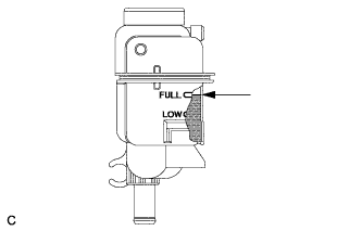
Slowly pour coolant into the radiator reservoir tank until it reaches the FULL line.
Coolant quantity 1.9 liter (2.0 US qts, 1.7 Imp. qts.) -
When using the intelligent tester:
-
Connect the intelligent tester to the DLC3.
-
Turn the power switch on (IG).
-
On the intelligent tester, enter the following menus: Powertrain / Hybrid Control / Active Test / Activate the Water Pump.
-
Keep the coolant at the FULL level in the reserve tank to compensate for the drop in coolant level when the air bleeds.
Standard Air bleeding from the coolant system is completed when the noise made by the water pump becomes smaller and the circulation of coolant in the reserve tank improves. Tech Tips
Loud noise made by the water pump and poor circulation of coolant in the reserve tank indicates that there is air in the coolant system.
-
-
When not using the intelligent tester:
-
Turn the power switch on (READY). [*1]
-
Turn the power switch off and keep the coolant at the FULL level in the reserve tank to compensate for the drop in coolant level when the air bleeds. [*2]
Note
-
Be sure to turn the power switch off before adding SLLC.
-
Do not work on the components in the engine compartment while the vehicle is in the READY-on state because the engine is in intermittent operation.
-
-
Repeat steps [*1] and [*2] until air bleeding from the coolant system is completed.
Standard Air bleeding from the coolant system is completed when the noise made by the water pump becomes smaller and the circulation of coolant in the reserve tank improves. Tech Tips
Loud noise made by the water pump and poor circulation of coolant in the reserve tank indicates that there is air in the coolant system.
-
-
Add coolant to the FULL mark of the reserve tank.
-
-
WARM UP COMPRESSOR
-
Keep the A/C switch on for at least 2 minutes to warm up the compressor.
Note
Be sure to warm up the compressor when turning the A/C on after removing and installing the cooler refrigerant lines (including the compressor), to prevent damage to the compressor.
-
-
INSPECT FOR REFRIGERANT LEAK
-
After recharging with refrigerant, inspect for refrigerant leaks using a halogen leak detector.
-
Carry out the test under the following conditions:
-
Turn the power switch off.
-
Secure good ventilation (the halogen leak detector may react to volatile gases which are not refrigerant, such as evaporated gasoline and exhaust gas).
-
Repeat the test 2 or 3 times.
-
Make sure that there is some refrigerant remaining in the refrigeration system.
When the compressor is off: approx. 392 to 588 kPa (4 to 6 kgf/cm2, 57 to 85 psi)
-
-
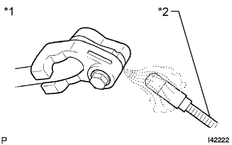
Text in Illustration *1 Inspect for Leak *2 Halogen Leak Detector Using a halogen leak detector, inspect for refrigerant leaks from the refrigerant lines.
-
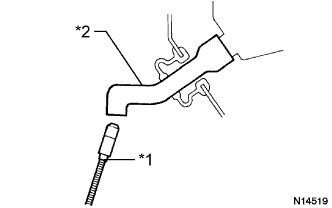
Text in Illustration *1 Halogen Leak Detector *2 Drain Hose Bring the halogen leak detector close to the drain hose with the detector's power off, and then turn the detector on.
Tech Tips
-
After the blower motor has stopped, let the cooling unit stand for more than 15 minutes.
-
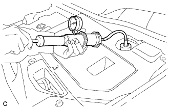
Bring the halogen leak detector sensor under the drain hose.
-
When bringing the halogen leak detector close to the drain hose, make sure that the halogen leak detector does not react to volatile gases. If it is not possible to avoid interference from volatile gases, the vehicle should be lifted up to allow testing.
-
-
If a refrigerant leak is not detected from the drain hose, remove the blower motor control from the cooling unit. Insert the halogen leak detector sensor into the unit and perform the test.
-
Disconnect the pressure switch connector and leave it for approximately 20 minutes. Bring the halogen leak detector close to the pressure switch and perform the test.
-
-
INSPECT FOR COOLANT LEAK (for Inverter)
-
Remove the reserve tank cap.
CAUTION:
To avoid the danger of being burned, do not remove the reserve tank cap while the coolant for the inverter is still hot.
-
Install the radiator cap tester.
-
Pump the radiator cap tester to 118 kPa (1.2 kgf/ cm2, 17 psi), and then check that the pressure does not drop.
Tech Tips
If the pressure drops, check the hoses, radiator, water pump, inverter with converter, and hybrid vehicle transaxle assembly for leaks.
-
Reinstall the reserve tank cap.
-
-
INSPECT HOOD SUB-ASSEMBLY
-
Inspect the hood sub-assembly Click here.
-
-
ADJUST HOOD SUB-ASSEMBLY
-
Adjust the hood sub-assembly Click here.
-