BRAKE PEDAL STROKE SENSOR INSTALLATION

Note
While the battery is connected, even if the power switch is off, the brake control system activates when the brake pedal is depressed or any door courtesy switch is turned on. Therefore, when servicing the brake system components, do not depress the brake pedal or open/close the doors while the battery is connected.
-
INSPECT AND ADJUST BRAKE PEDAL HEIGHT (for LHD)
-
Check the brake pedal height.
-
Turn back the carpet.
-
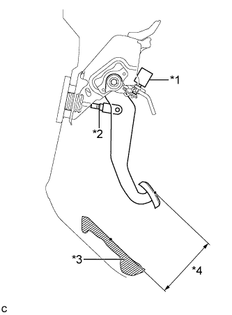
Text in Illustration *1 Stop Light Switch Assembly *2 Push Rod Clevis Lock Nut *3 Front Floor Footrest *4 Pedal Height Measure the shortest distance between the brake pedal surface and front floor footrest.
Pedal Height from Front Floor Footrest Brake Pedal Specification w/o Aluminum Pad 148.8 to 158.8 mm (5.86 to 6.25 in.) w/ Aluminum Pad 150.7 to 160.7 mm (5.93 to 6.33 in.)
-
-
Adjust the brake pedal height.
-
Remove the stop light switch assembly Click here.
-
Loosen the push rod clevis lock nut.
-
Adjust the brake pedal height by turning the push rod.
Pedal Height from Front Floor Footrest Brake Pedal Specification w/o Aluminum Pad 148.8 to 158.8 mm (5.86 to 6.25 in.) w/ Aluminum Pad 150.7 to 160.7 mm (5.93 to 6.33 in.) -
Tighten the push rod clevis lock nut.
- Torque:
- 26 N*m { 265 kgf*cm, 19 ft.*lbf }
-
Install and adjust the stop light switch assembly Click here.
Note
Do not depress the brake pedal.
-
-
-
INSPECT AND ADJUST BRAKE PEDAL HEIGHT (for RHD)
-
Check the brake pedal height.
-
Turn back the carpet.
-
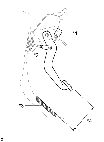
Text in Illustration *1 Stop Light Switch Assembly *2 Push Rod Clevis Lock Nut *3 No. 2 Dash Panel Insulator Pad *4 Pedal Height Measure the shortest distance between the brake pedal surface and No. 2 dash panel insulator pad.
Pedal Height from No. 2 Dash Panel Insulator Pad Brake Pedal Specification w/o Aluminum Pad 156.2 to 166.2 mm (6.15 to 6.54 in.) w/ Aluminum Pad 158.2 to 168.2 mm (6.23 to 6.62 in.)
-
-
Adjust the brake pedal height.
-
Remove the stop light switch assembly Click here.
-
Loosen the push rod clevis lock nut.
-
Adjust the brake pedal height by turning the push rod.
Pedal Height from No. 2 Dash Panel Insulator Pad Brake Pedal Specification w/o Aluminum Pad 156.2 to 166.2 mm (6.15 to 6.54 in.) w/ Aluminum Pad 158.2 to 168.2 mm (6.23 to 6.62 in.) -
Tighten the push rod clevis lock nut.
- Torque:
- 26 N*m { 265 kgf*cm, 19 ft.*lbf }
-
Install and adjust the stop light switch assembly Click here.
Note
Do not depress the brake pedal.
-
-
-
INSTALL BRAKE PEDAL STROKE SENSOR ASSEMBLY (for LHD)
Note
-
Do not drop the brake pedal stroke sensor assembly.
-
If the brake pedal stroke sensor assembly has been dropped, replace it with a new one.
-
When installing a new brake pedal stroke sensor assembly:
Note
Do not break the brake pedal stroke sensor assembly lever set pin before installing it with the bolts.
-
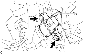
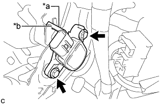
Text in Illustration *a Brake Pedal Stroke Sensor Assembly Lever *b Brake Pedal Groove Install a new brake pedal stroke sensor assembly with the 2 bolts.
- Torque:
- 8.5 N*m { 87 kgf*cm, 75 in.*lbf }
Note
-
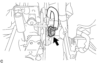
Engage the brake pedal stroke sensor assembly lever with the brake pedal groove.
-
Check that there is no foreign matter attached to the contact surface of the brake pedal stroke sensor assembly.
-
Check that the tip of the brake pedal stroke sensor assembly lever is protruding from the brake pedal groove.
-
Firmly depress the brake pedal and break the brake pedal stroke sensor assembly lever set pin, and remove it.
-
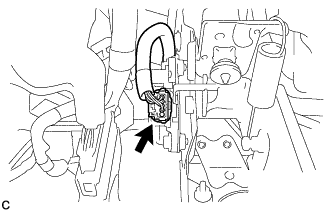
Connect the connector to the brake pedal stroke sensor assembly.
-
-
When reusing the brake pedal stroke sensor assembly:
-
Text in Illustration *a Brake Pedal Stroke Sensor Assembly Lever *b Brake Pedal Groove Temporarily install the brake pedal stroke sensor assembly with the 2 bolts.
Note
-
Engage the brake pedal stroke sensor assembly lever with the brake pedal groove.
-
Check that there is no foreign matter attached to the contact surface of the brake pedal stroke sensor assembly.
Tech Tips
Fully tighten the 2 bolts when adjusting the brake pedal stroke sensor assembly.
-
-
Connect the connector to the brake pedal stroke sensor assembly.
-
-
-
INSTALL BRAKE PEDAL STROKE SENSOR ASSEMBLY (for RHD)
Note
-
Do not drop the brake pedal stroke sensor assembly.
-
If the brake pedal stroke sensor assembly has been dropped, replace it with a new one.
-
When installing a new brake pedal stroke sensor assembly:
Note
Do not break the brake pedal stroke sensor assembly lever set pin before installing it with the bolts.
-
Text in Illustration *a Brake Pedal Stroke Sensor Assembly Lever *b Brake Pedal Groove Install a new brake pedal stroke sensor assembly with the 2 bolts.
- Torque:
- 8.5 N*m { 87 kgf*cm, 75 in.*lbf }
Note
-
Engage the brake pedal stroke sensor assembly lever with the brake pedal groove.
-
Check that there is no foreign matter attached to the contact surface of the brake pedal stroke sensor assembly.
-
Check that the tip of the brake pedal stroke sensor assembly lever is protruding from the brake pedal groove.
-
Firmly depress the brake pedal and break the brake pedal stroke sensor assembly lever set pin, and remove it.
-
Connect the connector to the brake pedal stroke sensor assembly.
-
-
When reusing the brake pedal stroke sensor assembly:
-
Text in Illustration *a Brake Pedal Stroke Sensor Assembly Lever *b Brake Pedal Groove Temporarily install the brake pedal stroke sensor assembly with the 2 bolts.
Note
-
Engage the brake pedal stroke sensor assembly lever with the brake pedal groove.
-
Check that there is no foreign matter attached to the contact surface of the brake pedal stroke sensor assembly.
Tech Tips
Fully tighten the 2 bolts when adjusting the brake pedal stroke sensor assembly.
-
-
Connect the connector to the brake pedal stroke sensor assembly.
-
-
-
ADJUST BRAKE PEDAL STROKE SENSOR ASSEMBLY (for LHD)
Note
When the brake pedal stroke sensor assembly is being reused, perform the following procedure to adjust it.
-
Connect the cable to the battery negative terminal.
-
Connect the intelligent tester to the DLC3.
-
Turn the power switch on (IG).
-
Turn the intelligent tester on.
-
Enter the following menus: Chassis / ABS/VSC/TRC / Data List "Stroke Sensor".
-
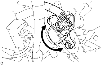
Read the stroke sensor value in the Data List, and turn the brake pedal stroke sensor assembly slowly to the right or left to adjust the output voltage so that it is within the following range.
Standard voltage (without the brake pedal depressed) 0.8 to 1.2 V -
Tighten the 2 bolts.
- Torque:
- 8.5 N*m { 87 kgf*cm, 75 in.*lbf }
Note
Do not depress the brake pedal after turning the power switch on (IG).
-
Turn the intelligent tester off and turn the power switch off.
-
Disconnect the cable from the battery negative terminal.
-
Disconnect the intelligent tester.
-
-
ADJUST BRAKE PEDAL STROKE SENSOR ASSEMBLY (for RHD)
Note
When the brake pedal stroke sensor assembly is being reused, perform the following procedure to adjust it.
-
Connect the cable to the battery negative terminal.
-
Connect the intelligent tester to the DLC3.
-
Turn the power switch on (IG).
-
Turn the intelligent tester on.
-
Enter the following menus: Chassis / ABS/VSC/TRC / Data List "Stroke Sensor".
-
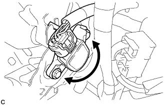
Read the stroke sensor value in the Data List, and turn the brake pedal stroke sensor assembly slowly to the right or left to adjust the output voltage so that it is within the following range.
Standard voltage (without the brake pedal depressed) 0.8 to 1.2 V -
Tighten the 2 bolts.
- Torque:
- 8.5 N*m { 87 kgf*cm, 75 in.*lbf }
Note
Do not depress the brake pedal after turning the power switch on (IG).
-
Turn the intelligent tester off and turn the power switch off.
-
Disconnect the cable from the battery negative terminal.
-
Disconnect the intelligent tester.
-
-
INSTALL DRIVER SIDE KNEE AIRBAG ASSEMBLY
-
CHECK AND CLEAR DTC
-
PERFORM LINEAR VALVE OFFSET LEARNING