ELECTRONICALLY CONTROLLED BRAKE SYSTEM, Diagnostic DTC:C1247/47, C1346/71, C1392/48

| DTC Code | DTC Name |
|---|---|
| C1247/47 | Stroke Sensor Malfunction |
| C1346/71 | Stroke Sensor Zero Point Learning Malfunction (Test Mode DTC) |
| C1392/48 | Stroke Sensor Zero Point Calibration Undone |
DESCRIPTION
The stroke sensor inputs the pedal stroke into the skid control ECU.
DTC C1346/71 will be cleared when the brake pedal stroke sensor sends a stroke sensor signal or when Test Mode ends. DTC C1346/71 is output only in Test Mode.
| DTC Code | INF Code | DTC Detection Condition | Trouble Area |
|---|---|---|---|
| C1247/47 | 171 | Sensor power source voltage (VCSK) is 4.67 V or less or 5.41 V or more for at least 0.2 seconds. |
|
| ↑ | 172 | Ratio of sensor output voltage 1 (SKS1) to sensor power source voltage (VCSK) is less than 5% or 90% or more for at least 0.2 seconds. |
|
| ↑ | 173 | Ratio of sensor output voltage 2 (SKS2) to sensor power source voltage (VCSK) is less than 5% or 90% or more for at least 0.2 seconds. | ↑ |
| ↑ | 174 | The stroke value converted from the sensor output 1 (SKS1) fluctuates due to noise. | ↑ |
| ↑ | 175 | The stroke value converted from the sensor output 2 (SKS2) fluctuates due to noise. | ↑ |
| ↑ | 181 | Information code 171, 172, 173, 174, 175, 182 or 183 is not output. | ↑ |
| ↑ | 182 | Difference between sensor output voltage 1 (SKS1) and sensor output voltage 2 (SKS2) differs. | ↑ |
| ↑ | 183 | Compared to sensor output voltage 1 (SKS1) and sensor output voltage 2 (SKS2), the master cylinder pressure sensor output voltage 1 (PMC1) and master cylinder pressure sensor voltage 2 (PMC2) are low. |
|
| C1392/48 | - | Zero point calibration of stroke sensor is unfinished. |
|
| C1346/71 | - | Detected only during Test Mode. |
|
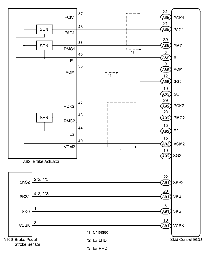
WIRING DIAGRAM
INSPECTION PROCEDURE
Note
When replacing the skid control ECU or brake pedal stroke sensor, perform initialization and calibration of the linear solenoid valve Click here.
Tech Tips
Check the condition of each related circuit connector before troubleshooting Click here.
PROCEDURE
-
CHECK BRAKE PEDAL
-
Check that the brake pedal and the brake pedal stroke sensor are properly installed and that the pedal can be operated normally.
-
Check and adjust the brake pedal height Click here for LHD, or Click here for RHD).
-
Adjust the brake pedal stroke sensor Click here for LHD, or Click here for RHD).
NEXT 
-
-
CHECK HARNESS AND CONNECTOR (SKID CONTROL ECU - BRAKE PEDAL STROKE SENSOR)
-
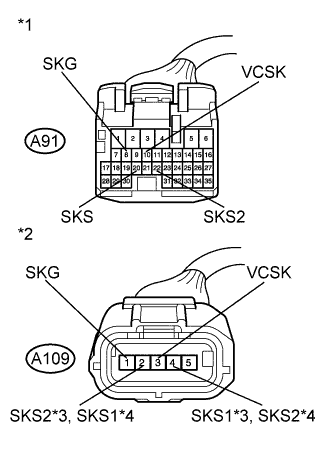
Text in Illustration *1 Front view of wire harness connector
(to Skid Control ECU)
*2 Front view of wire harness connector
(to Brake Pedal Stroke Sensor)
*3 for LHD *4 for RHD Make sure that there is no looseness at the locking part and the connecting part of the connectors.
-
Disconnect the skid control ECU connector and the brake pedal stroke sensor connector.
-
Check both the connector case and the terminal for deformation and corrosion.
OK No deformation or corrosion. -
Measure the resistance according to the value(s) in the table below.
Standard Resistance for LHD Tester Connection Condition Specified Condition A91-10 (VCSK) - A109-3 (VCSK) Always Below 1 Ω A91-10 (VCSK) - Body ground Always 10 kΩ or higher A91-8 (SKG) - A109-1 (SKG) Always Below 1 Ω A91-8 (SKG) - Body ground Always 10 kΩ or higher A91-20 (SKS) - A109-4 (SKS1) Always Below 1 Ω A91-20 (SKS) - Body ground Always 10 kΩ or higher A91-22 (SKS2) - A109-2 (SKS2) Always Below 1 Ω A91-22 (SKS2) - Body ground Always 10 kΩ or higher for RHD Tester Connection Condition Specified Condition A91-10 (VCSK) - A109-3 (VCSK) Always Below 1 Ω A91-10 (VCSK) - Body ground Always 10 kΩ or higher A91-8 (SKG) - A109-1 (SKG) Always Below 1 Ω A91-8 (SKG) - Body ground Always 10 kΩ or higher A91-20 (SKS) - A109-2 (SKS1) Always Below 1 Ω A91-20 (SKS) - Body ground Always 10 kΩ or higher A91-22 (SKS2) - A109-4 (SKS2) Always Below 1 Ω A91-22 (SKS2) - Body ground Always 10 kΩ or higher
NG 
REPAIR OR REPLACE HARNESS OR CONNECTOR
OK
-
-
PERFORM INITIALIZATION AND CALIBRATION OF LINEAR SOLENOID VALVE
-
Reconnect the skid control ECU connector and the brake pedal stroke sensor connector.
-
Perform initialization and calibration of the linear solenoid valve Click here.
NEXT
-
-
RECONFIRM DTC
-
Turn the power switch off.
-
Clear the DTCs Click here.
-
Perform a road test.
-
Check if the same DTC is recorded Click here.
Result Result Proceed to DTCs (C1247/47 and/or C1392/48) are output A DTCs (C1247/47 and C1392/48) are not output B
B
END
A
-
-
INSPECT SKID CONTROL ECU (SENSOR OUTPUT)
-
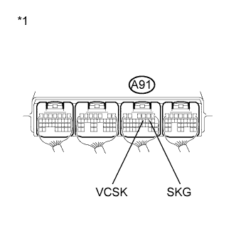
Text in Illustration *1 Component with harness connected
(Skid Control ECU)
Turn the power switch on (IG).
-
Measure the voltage according to the value(s) in the table below.
Standard Voltage Tester Connection Switch Condition Specified Condition A91-10 (VCSK) - Body ground Power switch on (IG) 4.5 to 5.5 V -
Turn the power switch off.
-
Measure the resistance according to the value(s) in the table below.
Standard Resistance Tester Connection Condition Specified Condition A91-8 (SKG) - Body ground Always Below 1 Ω
NG
REPLACE SKID CONTROL ECU Click here
OK
-
-
READ VALUE USING INTELLIGENT TESTER (BRAKE PEDAL STROKE SENSOR)
-
Mount a pedal effort gauge.
-
Connect the intelligent tester to the DLC3.
-
Turn the power switch on (IG).
-
Select the Data List on the intelligent tester Click here.
ABS/VSC/TRC Tester Display Measurement Item/Range Normal Condition Diagnostic Note Stroke Sensor Brake pedal stroke sensor /
Min.: 0 V, Max.: 5 V
When brake pedal is released:
0.8 to 1.2 V
Reading increases when brake pedal is depressed Stroke Sensor2 Brake pedal stroke sensor 2 /
Min.: 0 V, Max.: 5 V
When brake pedal is released:
3.8 to 4.2 V
Reading decreases when brake pedal is depressed -
When depressing the brake pedal with the amount of force listed in the table below, check that the output value displayed on the intelligent tester is within the standard voltage.
Tech Tips
The brake pedal must be depressed gradually.
Standard Voltage Brake Effort N (kgf, lbf) Stroke Sensor
(Data List Display)
Stroke Sensor2
(Data List Display)
50 (5, 11.2) 1.15 to 1.55 V 3.40 to 3.80 V 100 (10, 22.5) 1.30 to 1.70 V 3.25 to 3.65 V 150 (15, 33.7) 1.40 to 1.80 V 3.15 to 3.55 V 200 (20, 45.0) 1.50 to 1.90 V 3.05 to 3.45 V
NG
REPLACE BRAKE PEDAL STROKE SENSOR Click here
OK
-
-
CHECK HARNESS AND CONNECTOR (SKID CONTROL ECU - BRAKE ACTUATOR)
-
Make sure that there is no looseness at the locking part and the connecting part of the connectors.
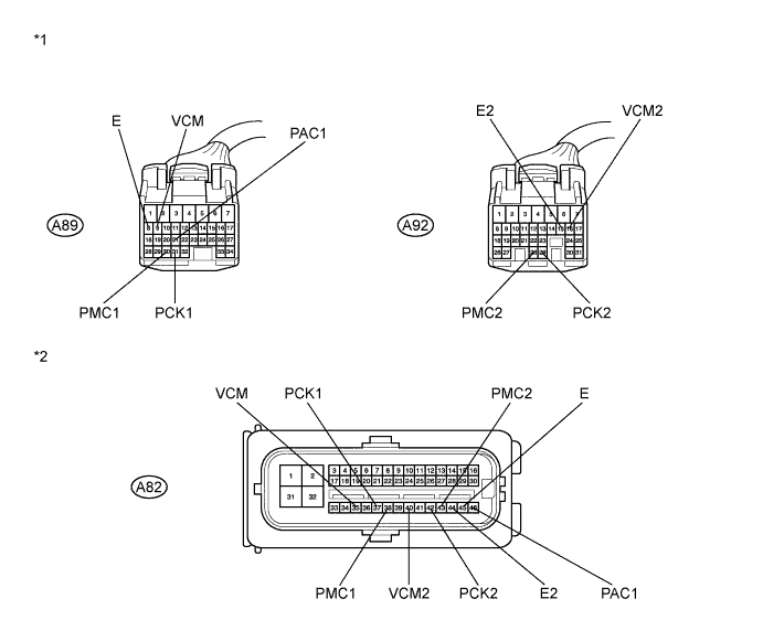
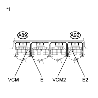
Text in Illustration *1 Front view of wire harness connector
(to Skid Control ECU)
*2 Front view of wire harness connector
(to Brake Actuator)
-
Disconnect the skid control ECU connectors and the brake actuator connector.
-
Measure the resistance according to the value(s) in the table below.
Standard Resistance Tester Connection Condition Specified Condition A89-9 (VCM) - A82-35 (VCM) Always Below 1 Ω A89-9 (VCM) - Body ground Always 10 kΩ or higher A89-21 (PAC1) - A82-46 (PAC1) Always Below 1 Ω A89-21 (PAC1) - Body ground Always 10 kΩ or higher A89-30 (PMC1) - A82-38 (PMC1) Always Below 1 Ω A89-30 (PMC1) - Body ground Always 10 kΩ or higher A89-8 (E) - A82-45 (E) Always Below 1 Ω A89-8 (E) - Body ground Always 10 kΩ or higher A89-31 (PCK1) - A82-37 (PCK1) Always Below 1 Ω A89-31 (PCK1) - Body ground Always 10 kΩ or higher A92-16 (VCM2) - A82-40 (VCM2) Always Below 1 Ω A92-16 (VCM2) - Body ground Always 10 kΩ or higher A92-28 (PMC2) - A82-43 (PMC2) Always Below 1 Ω A92-28 (PMC2) - Body ground Always 10 kΩ or higher A92-15 (E2) - A82-44 (E2) Always Below 1 Ω A92-15 (E2) - Body ground Always 10 kΩ or higher A92-29 (PCK2) - A82-42 (PCK2) Always Below 1 Ω A92-29 (PCK2) - Body ground Always 10 kΩ or higher
NG
REPAIR OR REPLACE HARNESS OR CONNECTOR
OK
-
-
INSPECT SKID CONTROL ECU (SENSOR OUTPUT)
-
Text in Illustration *1 Component with harness connected
(Skid Control ECU)
Reconnect the skid control ECU connectors and the brake actuator connector.
-
Turn the power switch on (IG).
-
Measure the voltage according to the value(s) in the table below.
Standard Voltage Tester Connection Switch Condition Specified Condition A89-9 (VCM) - Body ground Power switch on (IG) 4.75 to 5.25 V A92-16 (VCM2) - Body ground Power switch on (IG) 4.75 to 5.25 V -
Turn the power switch off.
-
Measure the resistance according to the value(s) in the table below.
Standard Resistance Tester Connection Condition Specified Condition A89-8 (E) - Body ground Always Below 1 Ω A92-15 (E2) - Body ground Always Below 1 Ω
NG
REPLACE SKID CONTROL ECU Click here
OK
-
-
READ VALUE USING INTELLIGENT TESTER (MASTER CYLINDER PRESSURE SENSOR)
-
Mount a pedal effort gauge.
-
Connect the intelligent tester to the DLC3.
-
Turn the power switch on (IG).
-
Select the Data List on the intelligent tester Click here.
ABS/VSC/TRC Tester Display Measurement Item/Range Normal Condition Diagnostic Note Master Cylinder Sensor Master cylinder pressure sensor 1 / Min.: 0 V, Max.: 5 V When brake pedal is released:
0.3 to 0.7 V
Reading increases when brake pedal is depressed Master Cylinder Sensor2 Master cylinder pressure sensor 2 / Min.: 0 V, Max.: 5 V When brake pedal is released:
0.3 to 0.7 V
Reading increases when brake pedal is depressed -
Check the output value of the master cylinder pressure sensor as the brake pedal is depressed.
Tech Tips
-
Check the value while electronically controlled brake system control is disabled and without servo assistance.
-
The brake warning light / yellow (minor malfunction) is on while electronically controlled brake system control is being disabled.
Standard Voltage Brake Effort N (kgf, lbf) Master Cylinder Sensor
(Data List Display)
Master Cylinder Sensor2
(Data List Display)
200 (20, 45.0) 0.90 to 1.30 V 0.90 to 1.30 V 500 (51, 112.4) 2.10 to 2.50 V 2.10 to 2.50 V -
NG
REPLACE BRAKE ACTUATOR ASSEMBLY Click here
OK 
REPLACE SKID CONTROL ECU Click here
-