| DTC Code | DTC Name |
|---|---|
| B279A | Theft Deterrent System Communication Line High Fixation |
DESCRIPTION
If the communication line (EFIO - IMI) to the ID code box (immobiliser code ECU) is stuck high (e. g. shorted to +B), the ECM stores this DTC.
| DTC No. | DTC Detection Condition | Trouble Area |
|---|---|---|
| B279A | When the communication line (EFIO - IMI) between ECM and ID code box (immobiliser code ECU) is stuck high. |
|
-
*: w/ Blocking System
INSPECTION PROCEDURE
-
If the ID code box (immobiliser code ECU) is replaced telephone transceiver assembly*, register the ECU code and ECU communication ID.
-
When the telephone transceiver assembly is replaced, it is necessary to set the contract mode.*
-
*: w/ Blocking System
PROCEDURE
- Click here
CHECK DTC OUTPUT
-
Clear the DTCs (Click here).
-
Recheck for DTCs (Click here).
Tip:If any DTCs other than DTC B279A are output, troubleshoot those DTCs first.
Result Result Proceed to DTC B279A is output A DTC B279A and other DTCs are output B
-
- Click here
SYSTEM CHECK
-
Check the vehicle specification.
Result Result Proceed to w/o Blocking System A w/ Blocking System B
-
- Click here
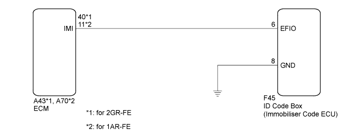
CHECK HARNESS AND CONNECTOR (ID CODE BOX - ECM)
-
Disconnect the ID code box (immobiliser code ECU) connector.
-
Disconnect the ECM connector.
-
Measure the resistance and voltage according to the value(s) in the table below.
Standard Resistance Table 1. for 2GR-FE Tester Connection Condition Specified Condition F45-6 (EFIO) - A43-40 (IMI) Always Below 1 Ω A43-40 (IMI) - Body ground Always 10 kΩ or higher Table 2. for 1AR-FE Tester Connection Condition Specified Condition F45-6 (EFIO) - A70-11 (IMI) Always Below 1 Ω A70-11 (IMI) - Body ground Always 10 kΩ or higher Standard Voltage Table 3. for 2GR-FE Tester Connection Condition Specified Condition A43-40 (IMI) - Body ground Always Below 1 V Table 4. for 1AR-FE Tester Connection Condition Specified Condition A70-11 (IMI) - Body ground Always Below 1 V
- OKClick here
- NGClick here
-
- Click here
CHECK ID CODE BOX (IMMOBILISER CODE ECU) (WAVEFORM)
-
Reconnect the ID code box (immobiliser code ECU) connector.
-
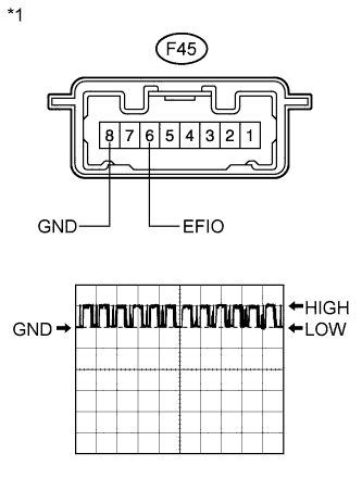
Reconnect the ECM connector.
-
Using an oscilloscope, check the waveform.
Waveform (Reference) Item Content Terminal No. (Symbol) F45-6 (EFIO) - F45-8 (GND) Tool Setting 5 V/DIV., 100 msec./DIV. Condition Engine switch on (IG) OK Waveform is output normally (see illustration). Result Result Proceed to NG A OK (for 2GR-FE) B OK (for 1AR-FE) C Table 5. Text in Illustration *1 Component with harness connected
(ID Code Box (Immobiliser Code ECU))
-
- Click here
REPLACE ID CODE BOX (IMMOBILISER CODE ECU)
-
Replace the ID code box (immobiliser code ECU).
- NEXTClick here
-
- Click here
ECU CODE REGISTRATION
-
Register the ECU code.
- NEXTClick here
-
- Click here
CHECK DTC OUTPUT
-
Clear the DTCs (Click here).
-
Recheck for DTCs (Click here).
OK DTC B279A is not output. Result Result Proceed to OK A NG (for 2GR-FE) B NG (for 1AR-FE) C
-
- Click here
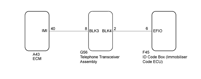
CHECK HARNESS AND CONNECTOR (ECM - TELEPHONE TRANSCEIVER ASSEMBLY)
-
Disconnect the G56 ECU connector.
-
Disconnect the A43 ECM connector.
-
Measure the resistance according to the value(s) in the table below.
Standard Resistance Tester Connection Condition Specified Condition G56-8 (BLK3) - A43-40 (IMI) Always Below 1 Ω A43-40 (IMI) - Body ground Always 10 kΩ or higher
- OKClick here
- NGClick here
-
- Click here
CHECK HARNESS AND CONNECTOR (ID CODE BOX (IMMOBILISER CODE ECU) - TELEPHONE TRANSCEIVER ASSEMBLY)
-
Disconnect the F45 ECU connector.
-
Measure the resistance according to the value(s) in the table below.
Standard Resistance Tester Connection Condition Specified Condition G56-2 (BLK4) - F45-6 (EFIO) Always Below 1 Ω F45-6 (EFIO) - Body ground Always 10 kΩ or higher
- OKClick here
- NGClick here
-
- Click here
REPLACE TELEPHONE TRANSCEIVER ASSEMBLY
-
Temporarily replace the telephone transceiver assembly with a new or known good one.
Tip:Refer to the Service Bulletin.
- NEXTClick here
-
- Click here
ECU CODE REGISTRATION
-
Register the ECU communication ID.
Tip:Refer to the Service Bulletin.
- NEXTClick here
-
- Click here
CLEAR DTC
-
Clear the DTCs (Click here).
- NEXTClick here
-
- Click here
CHECK DTC OUTPUT
-
Check for DTCs (Click here).
Tip:Before checking for DTCs, perform the "DTC Output Confirmation Operation" procedure.
OK DTC B279A is not output.
- OKClick here
- NGClick here
-
- Click here
REPLACE ID CODE BOX (IMMOBILISER CODE ECU)
-
Replace the ID code box (immobiliser code ECU) with a new one.
Tip:Refer to the Service Bulletin.
- NEXTClick here
-
- Click here
RESISTER RECOGNITION CODES
-
Register the key.
Tip:Refer to the Service Bulletin.
- NEXTClick here
-
- Click here
RESISTER ECU COMMUNICATION ID
-
Register the ECU communication ID.
Tip:Refer to the Service Bulletin.
- NEXTClick here
-
- Click here
CLEAR DTC
-
Clear the DTCs (Click here).
- NEXTClick here
-
- Click here
CHECK FOR DTC
-
Check for DTCs (Click here).
Tip:Before checking for DTCs, perform the "DTC Output Confirmation Operation" procedure.
OK DTC B279A is not output.
- OKClick here
- NGClick here
-
- Click here
GO TO DIAGNOSTIC TROUBLE CODE CHARTClick here
- Click here
REPAIR OR REPLACE HARNESS OR CONNECTOR
- Click here
REPLACE ECMClick here
- Click here
END (ID CODE BOX (IMMOBILISER CODE ECU) WAS DEFECTIVE)
- Click here
REPLACE ECMClick here
- Click here
END (TELEPHONE TRANSCEIVER ASSEMBLY WAS DEFECTIVE)
- Click here
END (ID CODE BOX (IMMOBILISER CODE ECU))
- Click here
REPLACE ECMClick here