PARKING BRAKE ASSEMBLY REASSEMBLY

Note
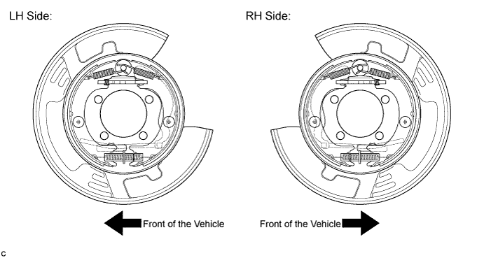
Before installation, apply high temperature grease to the parts indicated by arrows Click here.
-
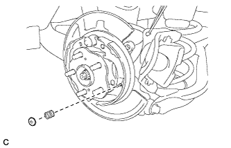
INSTALL PARKING BRAKE SHOE HOLD DOWN SPRING PIN
-
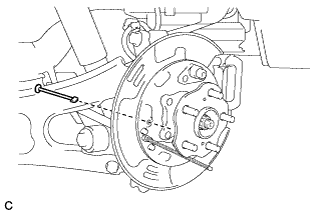
Install the parking brake shoe hold down spring pin (for front side).
-
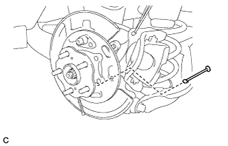
Install the parking brake shoe hold down spring pin (for rear side).
-
-
APPLY HIGH TEMPERATURE GREASE
-
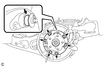
Apply high temperature grease to the areas of the backing plate which make contact with the shoe as shown in the illustration.
-
-
INSTALL PARKING BRAKE SHOE GUIDE PLATE SET BOLT
-
Apply adhesive to the threads of the parking brake shoe guide plate set bolt.
Adhesive Toyota Genuine Adhesive 1344, Three Bond 1344 or equivalent -
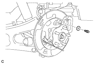
Install the parking brake shoe guide plate and parking brake shoe guide plate set bolt.
- Torque:
- 18 N*m { 184 kgf*cm, 13 ft.*lbf }
-
-
INSTALL PARKING BRAKE SHOE LEVER
-
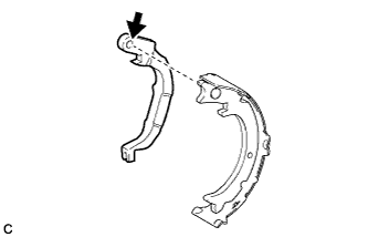
Apply high temperature grease to the areas of the parking brake shoe lever which make contact with the No. 2 parking brake shoe assembly.
-
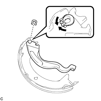
Install the parking brake shoe lever and shim to the No. 2 parking brake shoe assembly with a new C-washer as shown in the illustration.
-
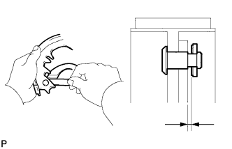
Using a feeler gauge, measure the clearance between the No. 2 parking brake shoe assembly and parking brake shoe lever.
Standard clearance Less than 0.35 mm (0.0138 in.) If the clearance is not as specified, replace the shim with one of the appropriate size.
Part No. Shim Thickness 90564-09184 0.3 mm (0.0118 in.) 90564-09185 0.6 mm (0.0236 in.) 90564-09186 0.9 mm (0.0354 in.)
-
-
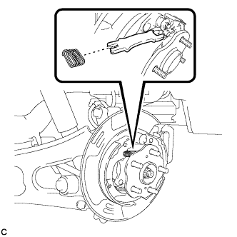
INSTALL NO. 2 PARKING BRAKE SHOE ASSEMBLY WITH PARKING BRAKE SHOE LEVER
-
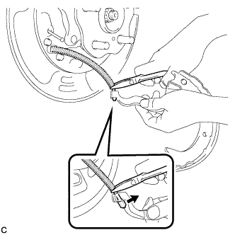
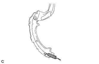
Using needle-nose pliers, connect the No. 3 parking brake cable assembly to the parking brake shoe lever as shown in the illustration.
Note
Be careful not to damage the No. 3 parking brake cable assembly.
-
-
INSTALL NO. 2 PARKING BRAKE SHOE RETURN TENSION SPRING
-
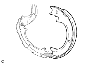
Install the No. 2 parking brake shoe return tension spring to the No. 2 parking brake shoe assembly.
-
-
INSTALL NO. 1 PARKING BRAKE SHOE ASSEMBLY
-
Connect the No. 2 parking brake shoe return tension spring to install the No. 1 parking brake shoe assembly.
-
-
INSTALL PARKING BRAKE SHOE ADJUSTING SCREW SET
-
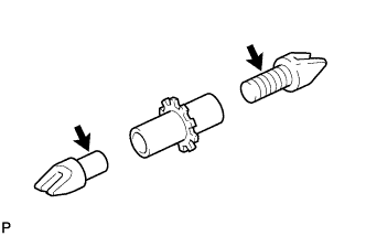
Apply high temperature grease to the parking brake shoe adjusting screw set as shown in the illustration.
-
Install the parking brake shoe adjusting screw set.
-
-
INSTALL NO. 2 PARKING BRAKE SHOE ASSEMBLY
-
Install the No. 2 parking brake shoe assembly to the backing plate with the No. 1 parking brake shoe hold down spring cup and parking brake shoe hold down spring.
-
-
INSTALL PARKING BRAKE SHOE LEVER STRUT
-
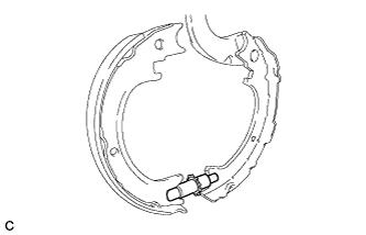
Install the parking brake shoe lever strut and parking brake shoe strut compression spring.
-
-
INSTALL NO. 1 PARKING BRAKE SHOE ASSEMBLY
-
Install the No. 1 parking brake shoe assembly to the backing plate with the No. 1 parking brake shoe hold down spring cup and parking brake shoe hold down spring.
-
-
INSTALL NO. 1 PARKING BRAKE SHOE RETURN TENSION SPRING
-
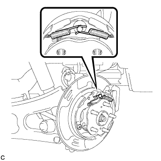
Install the 2 No. 1 parking brake shoe return tension springs.
Tech Tips
First install the front side spring and then the rear side spring.
-
-
CHECK PARKING BRAKE INSTALLATION
-
Check that each part is installed properly.
Note
There should be no oil or grease on the friction surfaces of the shoe lining and disc.
-
-
INSTALL REAR DISC
-
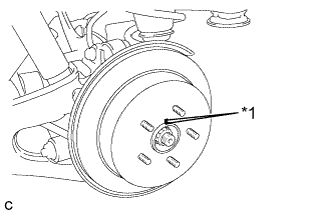
Text in Illustration *1 Matchmark Align the matchmarks and install the rear disc.
Note
When replacing the rear disc with a new one, select the installation position where the rear disc has minimal runout.
-
-
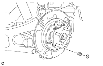
INSTALL PARKING BRAKE SHOE ADJUSTING HOLE PLUG
-
Install the parking brake shoe adjusting hole plug.
-
-
INSTALL REAR DISC BRAKE CALIPER ASSEMBLY
-
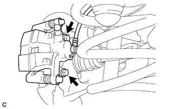
Install the rear disc brake caliper assembly with the 2 bolts.
- Torque:
- 78 N*m { 799 kgf*cm, 58 ft.*lbf }
-
-
INSTALL REAR WHEEL
- Torque:
- 103 N*m { 1050 kgf*cm, 76 ft.*lbf }
-
BED IN PARKING BRAKE SHOES TO DISCS
-
Drive the vehicle at about 50 km/h (31 mph) on a safe, level and dry road.
-
Depress the parking brake pedal with 150 N (15 kgf, 33.7 lbf) of force.
-
Drive the vehicle for about 400 m (0.25 mile) in this condition.
-
Repeat this procedure 3 times.
Note
Set a 5-minute interval between each procedure to prevent the brake assembly from overheating.
-
-
ADJUST PARKING BRAKE SHOE CLEARANCE AND PARKING BRAKE PEDAL TRAVEL (for LHD)
-
Remove the No. 1 instrument panel under cover sub-assembly Click here.
-
Completely release the parking brake pedal.
-
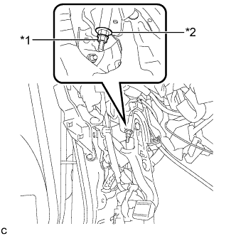
Text in Illustration *1 Lock Nut *2 Adjusting Nut Loosen the lock nut and the adjusting nut to completely release the parking brake cable.
-
Remove the rear wheels.
-
Temporarily install the hub nuts to the hub bolts.
Tech Tips
Securely install the hub nuts to the rear disc.
-
Remove the parking brake shoe adjusting hole plug Click here.
-
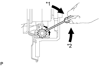
Text in Illustration *1 Expand *2 Contract Turn the shoe adjuster and expand the shoe until the disc locks.
-
Turn and contract the shoe adjuster until the disc can rotate smoothly.
Standard Return 8 notches. -
Check that there is no brake drag against the shoe.
-
Install the parking brake shoe adjusting hole plug Click here.
-
Turn the adjusting nut until the parking brake pedal travel is corrected to be within the specified range.
Parking brake pedal travel 7 to 10 notches at 300 N (31 kgf, 67.5 lbf) -
Text in Illustration *1 Lock Nut *2 Adjusting Nut Using a wrench or an equivalent tool, hold the adjusting nut and tighten the lock nut.
- Torque:
- 7.0 N*m { 71 kgf*cm, 62 in.*lbf }
-
Operate the parking brake pedal 3 to 4 times, and check the parking brake pedal travel.
-
Check that there is no brake drag against the shoe.
-
Remove the hub nuts from the hub bolts.
-
Install the rear wheels.
- Torque:
- 103 N*m { 1050 kgf*cm, 76 ft.*lbf }
-
Install the No. 1 instrument panel under cover sub-assembly Click here.
-
-
ADJUST PARKING BRAKE SHOE CLEARANCE AND PARKING BRAKE PEDAL TRAVEL (for RHD)
-
Remove the No. 1 instrument panel under cover sub-assembly Click here.
-
Completely release the parking brake pedal.
-
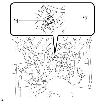
Text in Illustration *1 Lock Nut *2 Adjusting Nut Loosen the lock nut and the adjusting nut to completely release the parking brake cable.
-
Remove the rear wheels.
-
Temporarily install the hub nuts to the hub bolts.
Tech Tips
Securely install the hub nuts to the rear disc.
-
Remove the shoe adjusting hole plug Click here.
-
Text in Illustration *1 Expand *2 Contract Turn the shoe adjuster and expand the shoe until the disc locks.
-
Turn and contract the shoe adjuster until the disc can rotate smoothly.
Standard Return 8 notches. -
Check that there is no brake drag against the shoe.
-
Install the shoe adjusting hole plug Click here.
-
Turn the adjusting nut until the parking brake pedal travel is corrected to be within the specified range.
Parking brake pedal travel 7 to 10 notches at 300 N (31 kgf, 67.5 lbf) -
Text in Illustration *1 Lock Nut *2 Adjusting Nut Using a wrench or an equivalent tool, hold the adjusting nut and tighten the lock nut.
- Torque:
- 7.0 N*m { 71 kgf*cm, 62 in.*lbf }
-
Operate the parking brake pedal 3 to 4 times, and check the parking brake pedal travel.
-
Check that there is no brake drag against the shoe.
-
Remove the hub nuts from the hub bolts.
-
Install the rear wheels.
- Torque:
- 103 N*m { 1050 kgf*cm, 76 ft.*lbf }
-
Install the No. 1 instrument panel under cover sub-assembly Click here.
-