REAR BRAKE INSTALLATION

Tech Tips
-
Use the same procedure for the RH side and LH side.
-
The following procedure is for the LH side.
-
INSTALL REAR DISC
-
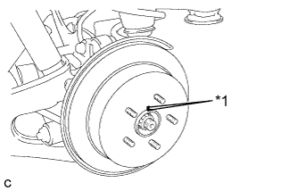
Text in Illustration *1 Matchmark Align the matchmarks and install the rear disc.
Note
When replacing the rear disc with a new one, select the installation position where the rear disc has minimal runout.
-
-
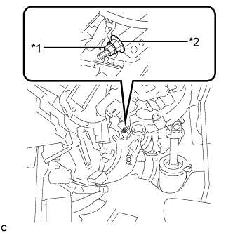
INSTALL PARKING BRAKE SHOE ADJUSTING HOLE PLUG
-
Install the parking brake shoe adjusting hole plug.
-
-
INSTALL REAR DISC BRAKE CYLINDER MOUNTING
-
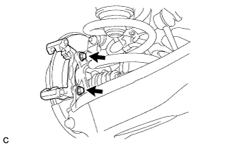
Install the rear disc brake cylinder mounting to the rear axle carrier sub-assembly with the 2 bolts.
- Torque:
- 78 N*m { 799 kgf*cm, 58 ft.*lbf }
-
-
INSTALL REAR DISC BRAKE BUSHING DUST BOOT
-
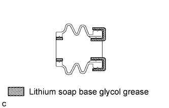
Apply a light layer of lithium soap base glycol grease to the entire circumference of 2 new rear disc brake bushing dust boots.
Tech Tips
Apply at least 0.3 g (0.01 oz.) of lithium soap base glycol grease to each rear disc brake bushing dust boot.
-
Install the 2 rear disc brake bushing dust boots to the rear disc brake cylinder mounting.
-
-
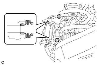
INSTALL NO. 2 REAR DISC BRAKE CYLINDER SLIDE PIN
-
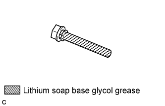
Apply a light layer of lithium soap base glycol grease to the sliding part and the seal surface of the No. 2 rear disc brake cylinder slide pin.
-
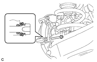
Install the No. 2 rear disc brake cylinder slide pin to the rear brake cylinder mounting.
-
Push the No. 2 rear disc brake cylinder slide pin into the rear disc brake bushing dust boot to align them.
-
-
INSTALL REAR DISC BRAKE CYLINDER SLIDE BUSHING
-
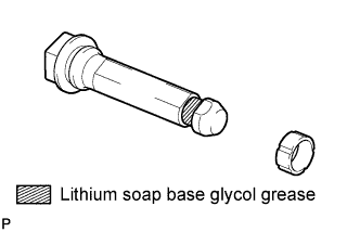
Apply a light layer of lithium soap base glycol grease to the contact surface of the No. 1 rear disc brake cylinder slide pin.
-
Install a new rear disc brake cylinder slide bushing to the No. 1 rear disc brake cylinder slide pin.
-
-
INSTALL NO. 1 REAR DISC BRAKE CYLINDER SLIDE PIN
-
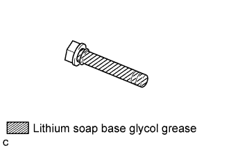
Apply a light layer of lithium soap base glycol grease to the sliding part and the seal surface of the No. 1 rear disc brake cylinder slide pin.
-
Install the No. 1 rear disc brake cylinder slide pin to the rear disc brake cylinder mounting.
-
Push the No. 1 rear disc brake cylinder slide pin into the rear disc brake bushing dust boot to align them.
-
-
INSTALL REAR DISC BRAKE PAD SUPPORT PLATE
-
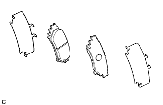
Install the 2 No. 1 rear disc brake pad support plates and 2 No. 2 rear disc brake pad support plates to the rear disc brake cylinder mounting.
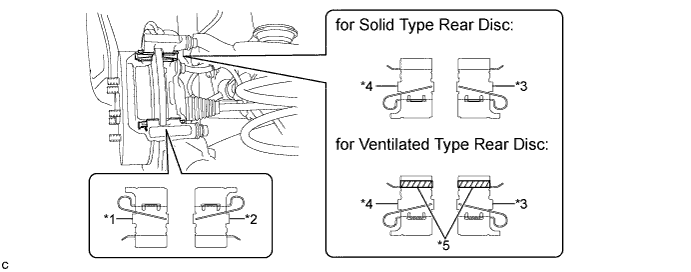
Text in Illustration for Solid Type Rear Disc for Ventilated Type Rear Disc *1 No. 1 Rear Disc Brake Pad Support Plate No. 1 Rear Disc Brake Pad Support Plate *2 No. 2 Rear Disc Brake Pad Support Plate No. 2 Rear Disc Brake Pad Support Plate *3 No. 1 Rear Disc Brake Pad Support Plate No. 1 Rear Disc Brake Pad Support Plate with Tape *4 No. 2 Rear Disc Brake Pad Support Plate No. 2 Rear Disc Brake Pad Support Plate with Tape *5 - Tape Note
-
Be sure to install the No. 1 rear disc brake pad support plates and the No. 2 rear disc brake pad support plates to the correct positions and directions.
-
The rear disc brake pad support plates with tape is installed in the upper portion (for ventilated type rear disc brake).
-
-
-
INSTALL PAD WEAR INDICATOR PLATE
-
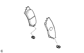
Install the 2 pad wear indicators to the rear disc brake pads.
Note
Install the pad wear indicators and rear anti-squeal shims in the correct positions and directions.
-
-
INSTALL REAR DISC BRAKE ANTI-SQUEAL SHIM
-
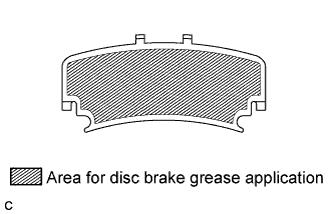
Apply disc brake grease to the inside of the 2 rear disc brake anti-squeal shims as shown in the illustration.
Note
-
When replacing worn pads, the rear disc brake anti-squeal shims must be replaced together with the pads.
-
Install the shims in the correct positions and directions.
-
Apply disc brake grease to the area that contacts the rear disc brake anti-squeal shims.
-
Disc brake grease can come out slightly from the area where the rear disc brake anti-squeal shims are installed.
-
Make sure that disc brake grease is not applied onto the lining surface.
-
-
Install the rear disc brake anti-squeal shims to each of the 2 rear disc brake pads.
-
-
INSTALL REAR DISC BRAKE PAD
-
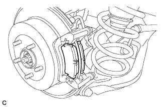
Install the 2 rear disc brake pads to the rear disc brake cylinder mounting.
-
-
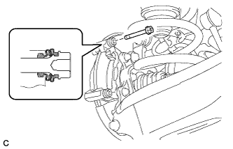
INSTALL REAR DISC BRAKE CYLINDER ASSEMBLY
-
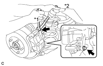
Text in Illustration *1 Hold *2 Turn Hold the 2 rear disc brake cylinder slide pins and install the rear disc brake cylinder assembly to the rear disc brake cylinder mounting with the 2 bolts.
- Torque:
- 27 N*m { 270 kgf*cm, 20 ft.*lbf }
-
-
CONNECT REAR FLEXIBLE HOSE
-
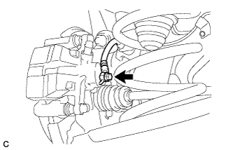
Connect the rear flexible hose to the rear disc brake cylinder assembly with a new union bolt and a new gasket.
- Torque:
- 30 N*m { 306 kgf*cm, 22 ft.*lbf }
-
-
FILL RESERVOIR WITH BRAKE FLUID
-
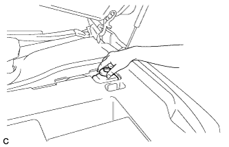
Remove the brake master cylinder reservoir filler cap assembly.
-
Fill the reservoir with brake fluid.
Brake Fluid SAE J1703 or FMVSS No. 116 DOT 3 Note
Make sure that there is sufficient brake fluid in the reservoir.
-
-
BLEED BRAKE LINE
Note
-
Bleed the brake line of the wheel farthest from the master cylinder first.
-
Add brake fluid to keep the level between the MIN and MAX lines of the reservoir while bleeding the brakes.
-
Depress the brake pedal several times, and then loosen the bleeder plug with the pedal depressed*1.
-
When fluid stops coming out, tighten the bleeder plug, and then release the brake pedal*2.
-
Repeat *1 and *2 until all the air in the fluid is completely bled out.
-
Tighten the bleeder plug completely.
- Torque:
- front bleeder plug
- 8.3 N*m { 85 kgf*cm, 73 in.*lbf }
- rear bleeder plug
- 11 N*m { 110 kgf*cm, 8 ft.*lbf }
-
Repeat the above procedure for each wheel to bleed the brake line.
-
-
INSPECT FOR BRAKE FLUID LEAK
-
INSPECT FLUID LEVEL
-
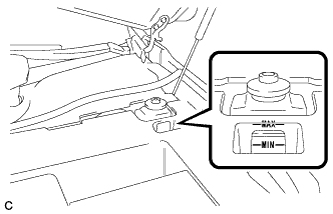
Check the fluid level.
If the brake fluid level is lower than the MIN line, check for leaks and inspect the disc brake pads. If necessary, refill the reservoir with brake fluid to the MAX line after repair or replacement.
Brake Fluid SAE J1703 or FMVSS No. 116 DOT 3
-
-
ADJUST PARKING BRAKE SHOE CLEARANCE AND PARKING BRAKE PEDAL TRAVEL (for LHD)
-
Remove the No. 1 instrument panel under cover sub-assembly Click here.
-
Completely release the parking brake pedal.
-
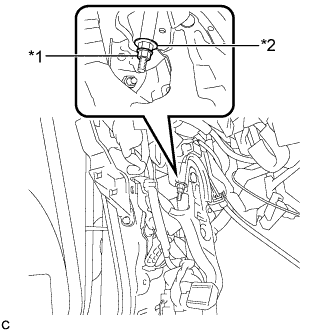
Text in Illustration *1 Lock Nut *2 Adjusting Nut Loosen the lock nut and the adjusting nut to completely release the parking brake cable.
-
Remove the rear wheels.
-
Temporarily install the hub nuts to the hub bolts.
Tech Tips
Securely install the hub nuts to the rear disc.
-
Remove the parking brake shoe adjusting hole plug Click here.
-
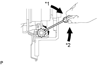
Text in Illustration *1 Expand *2 Contract Turn the shoe adjuster and expand the shoe until the disc locks.
-
Turn and contract the shoe adjuster until the disc can rotate smoothly.
Standard Return 8 notches. -
Check that there is no brake drag against the shoe.
-
Install the parking brake shoe adjusting hole plug Click here.
-
Turn the adjusting nut until the parking brake pedal travel is corrected to be within the specified range.
Parking brake pedal travel 7 to 10 notches at 300 N (31 kgf, 67.5 lbf) -
Text in Illustration *1 Lock Nut *2 Adjusting Nut Using a wrench or an equivalent tool, hold the adjusting nut and tighten the lock nut.
- Torque:
- 7.0 N*m { 71 kgf*cm, 62 in.*lbf }
-
Operate the parking brake pedal 3 to 4 times, and check the parking brake pedal travel.
-
Check that there is no brake drag against the shoe.
-
Remove the hub nuts from the hub bolts.
-
Install the rear wheels.
- Torque:
- 103 N*m { 1050 kgf*cm, 76 ft.*lbf }
-
Install the No. 1 instrument panel under cover sub-assembly Click here.
-
-
ADJUST PARKING BRAKE SHOE CLEARANCE AND PARKING BRAKE PEDAL TRAVEL (for RHD)
-
Remove the No. 1 instrument panel under cover sub-assembly Click here.
-
Completely release the parking brake pedal.
-
Text in Illustration *1 Lock Nut *2 Adjusting Nut Loosen the lock nut and the adjusting nut to completely release the parking brake cable.
-
Remove the rear wheels.
-
Temporarily install the hub nuts to the hub bolts.
Tech Tips
Securely install the hub nuts to the rear disc.
-
Remove the shoe adjusting hole plug Click here.
-
Text in Illustration *1 Expand *2 Contract Turn the shoe adjuster and expand the shoe until the disc locks.
-
Turn and contract the shoe adjuster until the disc can rotate smoothly.
Standard Return 8 notches. -
Check that there is no brake drag against the shoe.
-
Install the shoe adjusting hole plug Click here.
-
Turn the adjusting nut until the parking brake pedal travel is corrected to be within the specified range.
Parking brake pedal travel 7 to 10 notches at 300 N (31 kgf, 67.5 lbf) -
Text in Illustration *1 Lock Nut *2 Adjusting Nut Using a wrench or an equivalent tool, hold the adjusting nut and tighten the lock nut.
- Torque:
- 7.0 N*m { 71 kgf*cm, 62 in.*lbf }
-
Operate the parking brake pedal 3 to 4 times, and check the parking brake pedal travel.
-
Check that there is no brake drag against the shoe.
-
Remove the hub nuts from the hub bolts.
-
Install the rear wheels.
- Torque:
- 103 N*m { 1050 kgf*cm, 76 ft.*lbf }
-
Install the No. 1 instrument panel under cover sub-assembly Click here.
-
-
INSTALL REAR WHEEL
- Torque:
- 103 N*m { 1050 kgf*cm, 76 ft.*lbf }