REAR SUSPENSION MEMBER (for AWD) INSTALLATION

-
INSTALL HOLE PLUG
-
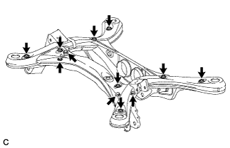
Install the 12 hole plugs to the rear suspension member sub-assembly as shown in the illustration.
Tech Tips
The upper and lower suspension member hole plug shapes are different.
-
-
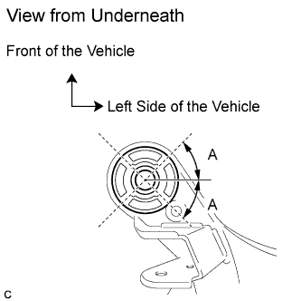
INSTALL REAR SUSPENSION MEMBER FRONT BODY MOUNTING CUSHION (for LH Side)
-
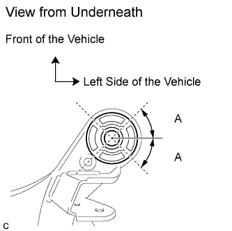
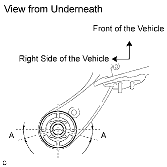
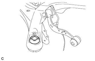
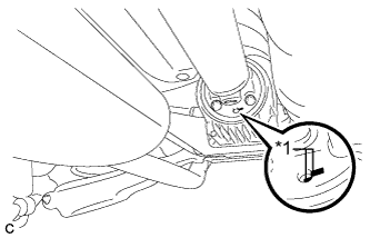
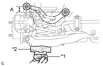
Temporarily install the rear suspension member front body mounting cushion (LH Side) while confirming the installation direction.
Standard (A) 40° to 50° -
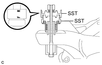
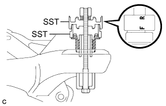
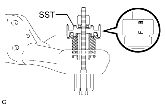
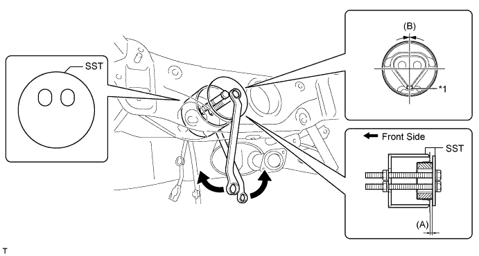
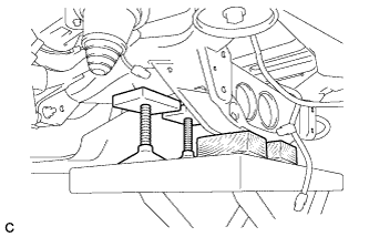
Install SST as shown in the illustration.
- SST
- 09527-17011
- 09830-10010 ( 09830-01010, 09830-01020, 09830-01030, 09830-01060 )
Note
Apply a small amount of grease to the threads and tip of SST (center bolt) before use.
Tech Tips
Use SST with the "F" mark facing the rear suspension member front body mounting cushion.
-
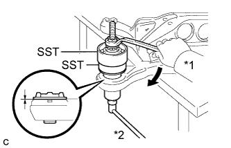
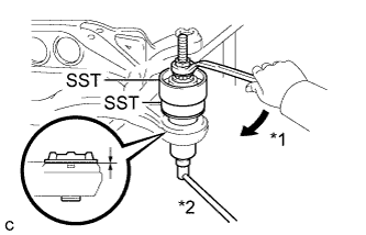
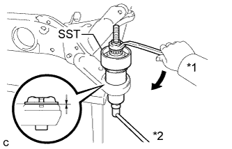
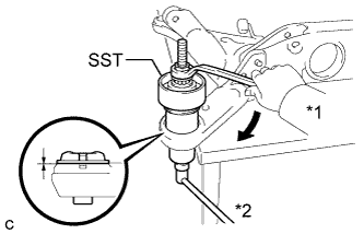
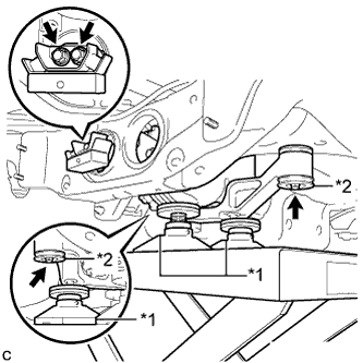
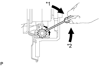
Text in Illustration *1 Turn *2 Hold Using SST, install the rear suspension member front body mounting cushion (LH Side) until there is no clearance between the rear suspension member sub-assembly and the rear suspension member front body mounting cushion (LH Side).
- SST
- 09527-17011
- 09830-10010 ( 09830-01010, 09830-01020, 09830-01030, 09830-01060 )
Note
If the rear suspension member sub-assembly is scratched, apply paint to the scratched areas of the rear suspension member sub-assembly.
-
Remove SST from the rear suspension member sub-assembly.
-
-
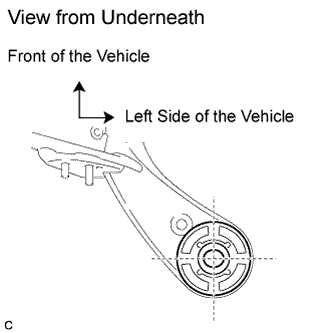
INSTALL REAR SUSPENSION MEMBER FRONT BODY MOUNTING CUSHION (for RH Side)
-
Temporarily install the rear suspension member front body mounting cushion (RH Side) while confirming the installation direction.
Standard (A) 40° to 50° -
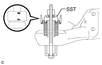
Install SST as shown in the illustration.
- SST
- 09527-17011
- 09830-10010 ( 09830-01010, 09830-01020, 09830-01030, 09830-01060 )
Note
Apply a small amount of grease to the threads and tip of SST (center bolt) before use.
Tech Tips
Use SST with the "F" mark facing the rear suspension member front body mounting cushion.
-
Text in Illustration *1 Turn *2 Hold Using SST, install the rear suspension member front body mounting cushion (RH Side) until there is no clearance between the rear suspension member sub-assembly and the rear suspension member front body mounting cushion (RH Side).
- SST
- 09527-17011
- 09830-10010 ( 09830-01010, 09830-01020, 09830-01030, 09830-01060 )
Note
If the rear suspension member sub-assembly is scratched, apply paint to the scratched areas of the rear suspension member sub-assembly.
-
Remove SST from the rear suspension member sub-assembly.
-
-
INSTALL REAR SUSPENSION MEMBER REAR BODY MOUNT CUSHION LH
-
Temporarily install the rear suspension member rear body mounting cushion LH while confirming the installation direction.
-
Install SST as shown in the illustration.
- SST
- 09830-10010 ( 09830-01010, 09830-01020, 09830-01030, 09830-01060 )
Note
Apply a small amount of grease to the threads and tip of SST (center bolt) before use.
Tech Tips
Use SST with the "F" mark facing the rear suspension member rear body mounting cushion.
-
Text in Illustration *1 Turn *2 Hold Using SST, install the rear suspension member rear body mounting cushion LH until there is no clearance between the rear suspension member sub-assembly and the rear suspension member rear body mounting cushion LH.
- SST
- 09830-10010 ( 09830-01010, 09830-01020, 09830-01030, 09830-01060 )
Note
If the rear suspension member sub-assembly is scratched, apply paint to the scratched areas of the rear suspension member sub-assembly.
-
Remove SST from the rear suspension member sub-assembly.
-
-
INSTALL REAR SUSPENSION MEMBER REAR BODY MOUNT CUSHION RH
-
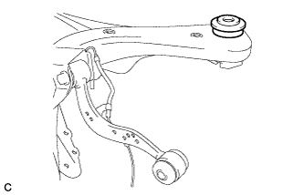
Temporarily install the rear suspension member rear body mounting cushion RH while confirming the installation direction.
Standard (A) 10° to 20° -
Install SST as shown in the illustration.
- SST
- 09830-10010 ( 09830-01010, 09830-01020, 09830-01030, 09830-01060 )
Note
Apply a small amount of grease to the threads and tip of SST (center bolt) before use.
Tech Tips
Use SST with the "F" mark facing the rear suspension member rear body mounting cushion.
-
Text in Illustration *1 Turn *2 Hold Using SST, install the rear suspension member rear body mounting cushion RH until there is no clearance between the rear suspension member sub-assembly and the rear suspension member rear body mounting cushion RH.
- SST
- 09830-10010 ( 09830-01010, 09830-01020, 09830-01030, 09830-01060 )
Note
If the rear suspension member sub-assembly is scratched, apply paint to the scratched areas of the rear suspension member sub-assembly.
-
Remove SST from the rear suspension member sub-assembly.
-
-
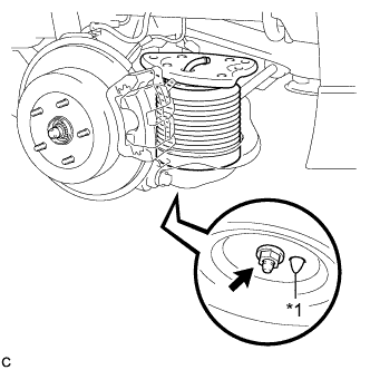
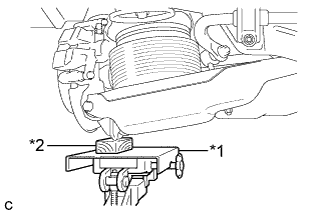
INSTALL REAR DIFFERENTIAL MOUNT CUSHION
-
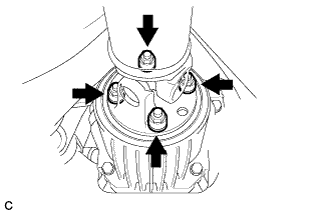
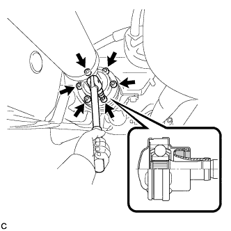
Using SST, install a new rear differential mount cushion.
Text in Illustration *1 Protrusion - - - SST
- 09570-48010
(A) 9.8 to 10.8 mm (0.386 to 0.425 in.) (B) +/- 3° Note
-
Apply grease to the threads of the SST bolts before use.
-
Do not set SST in the wrong direction.
-
Be sure to use SST in the correct combination.
-
Install the rear differential mount cushion within +/- 3° from the center.
-
Temporarily install the rear differential mount cushion to the rear suspension member before installing SST to prevent the rear differential mount cushion from being tilted.
-
Install the rear differential mount cushion so that the protrusion is positioned upward.
-
Make sure that SST contacts the entire rear differential mount cushion seating surface.
-
Do not slant the SST bolts.
-
Tighten the 2 SST bolts equally into the 2 rear differential mount cushion holes.
-
-
INSTALL REAR UPPER CONTROL ARM ASSEMBLY LH
-
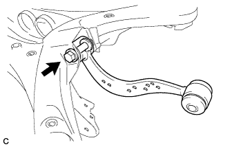
Temporarily install the rear upper control arm assembly LH to the rear suspension member sub-assembly with the bolt and nut.
Note
-
Insert the bolt with the threaded end facing the rear side of the vehicle.
-
Since the stopper nut is used, tighten the bolt.
-
-
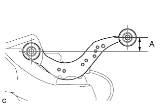
Set the rear upper control arm assembly LH in the tightening position as shown in the illustration.
Standard Length (A) 24.3 mm (0.957 in.) -
Fully tighten the bolt in the tightening position.
- Torque:
- 120 N*m { 1224 kgf*cm, 89 ft.*lbf }
Note
Since the stopper nut is used, tighten the bolt.
-
-
INSTALL REAR UPPER CONTROL ARM ASSEMBLY RH
Tech Tips
Perform the same procedure as the LH side.
-
INSTALL REAR SPEED SENSOR LH
-
Install the rear speed sensor LH with the 2 bolts and nut as shown in the illustration.
- Torque:
- Bolt
- 8.0 N*m { 82 kgf*cm, 71 in.*lbf }
- Nut
- 9.0 N*m { 92 kgf*cm, 80 in.*lbf }
Note
Do not twist the rear speed sensor LH when connecting it.
-
-
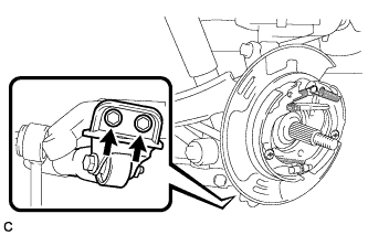
INSTALL REAR SPEED SENSOR RH
-
Install the rear speed sensor RH with the 2 bolts and nut as shown in the illustration.
- Torque:
- Bolt
- 8.0 N*m { 82 kgf*cm, 71 in.*lbf }
- Nut
- 9.0 N*m { 92 kgf*cm, 80 in.*lbf }
Note
Do not twist the rear speed sensor RH when connecting it.
-
-
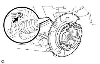
INSTALL REAR HEIGHT CONTROL SENSOR SUB-ASSEMBLY RH
-
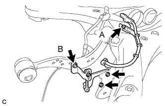
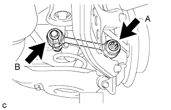
Install the rear height control sensor sub-assembly RH to the rear suspension member sub-assembly with the bolt (A) and 2 nuts.
- Torque:
- 5.0 N*m { 51 kgf*cm, 44 in.*lbf }
Note
Do not twist the rear height control sensor wire when connecting it.
-
Install the rear height control sensor sub-assembly RH to the rear upper control arm assembly RH with the bolt (B).
- Torque:
- 5.4 N*m { 55 kgf*cm, 48 in.*lbf }
-
-
INSTALL REAR HEIGHT CONTROL SENSOR SUB-ASSEMBLY LH (w/ Air Suspension)
-
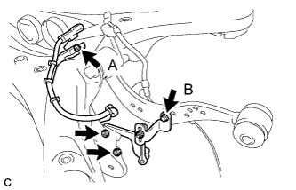
Install the rear height control sensor sub-assembly LH to the rear suspension member sub-assembly with the bolt (A) and 2 nuts.
- Torque:
- 5.0 N*m { 51 kgf*cm, 44 in.*lbf }
Note
Do not twist the rear height control sensor wire when connecting it.
-
Install the rear height control sensor sub-assembly LH to the rear upper control arm assembly LH with the bolt (B).
- Torque:
- 5.4 N*m { 55 kgf*cm, 48 in.*lbf }
-
-
INSTALL REAR SUSPENSION MEMBER UPPER STOPPER
-
Install the 2 rear suspension member upper stoppers as shown in the illustration.
Note
Be sure to install the rear suspension member upper stoppers in the correct direction shown in the illustration.
-
-
INSTALL REAR SUSPENSION MEMBER REAR UPPER STOPPER
-
Install the 2 rear suspension member rear upper stoppers as shown in the illustration.
-
-
TEMPORARILY TIGHTEN REAR NO. 1 SUSPENSION ARM ASSEMBLY LH
-
Temporarily tighten the rear No. 1 suspension arm assembly LH to the rear suspension member sub-assembly with the bolt and nut.
Note
-
Insert the bolt with the threaded end facing the rear side of the vehicle.
-
Since the stopper nut is used, tighten the bolt.
-
Fully tighten the bolt after stabilizing the suspension.
-
-
-
TEMPORARILY TIGHTEN REAR NO. 1 SUSPENSION ARM ASSEMBLY RH
Tech Tips
Perform the same procedure as the LH side.
-
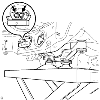
INSTALL REAR SUSPENSION MEMBER SUB-ASSEMBLY
-
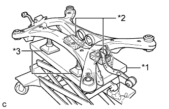
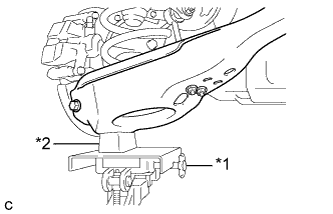
Text in Illustration *1 Jack *2 Wooden Block *3 Attachment Support the rear suspension member with a jack using 2 wooden blocks and 2 attachments or equivalent tools as shown in the illustration.
Note
Make sure to secure the rear suspension member to prevent it from dropping.
Tech Tips
Keep the suspension member level.
-
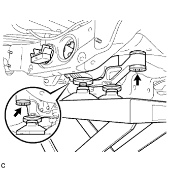
Raise the rear suspension member until there is no clearance between the rear suspension member and the body.
Note
When raising the rear suspension member, be careful not to damage the vehicle body or other components installed on the vehicle.
-
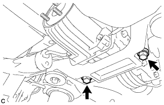
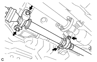
Install the rear suspension member with the 2 rear lower suspension braces, 2 rear lower suspension member stoppers, 4 bolts and 2 nuts.
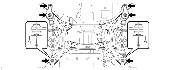
Text in Illustration *1 Rear Lower Suspension Brace - - - Torque:
- Bolt
- 158 N*m { 1612 kgf*cm, 117 ft.*lbf }
- Nut
- 32 N*m { 327 kgf*cm, 24 ft.*lbf }
Note
Be sure to install the rear suspension member with the rear lower suspension braces facing in the correct direction as shown in the illustration.
-
Lower the jack.
-
-
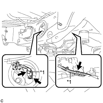
INSTALL FRAME WIRE
-
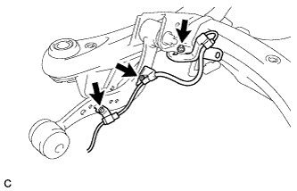
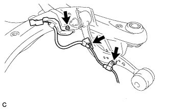
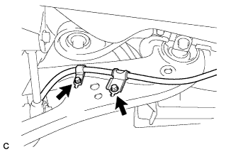
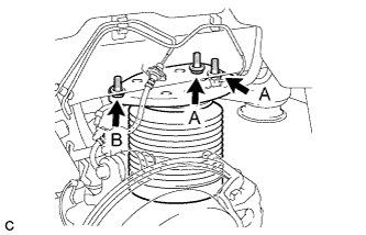
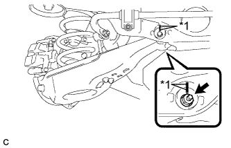
Install the bolt and engage the clamps, and then connect the connectors to install the frame wire to the rear suspension member as shown in the illustration.
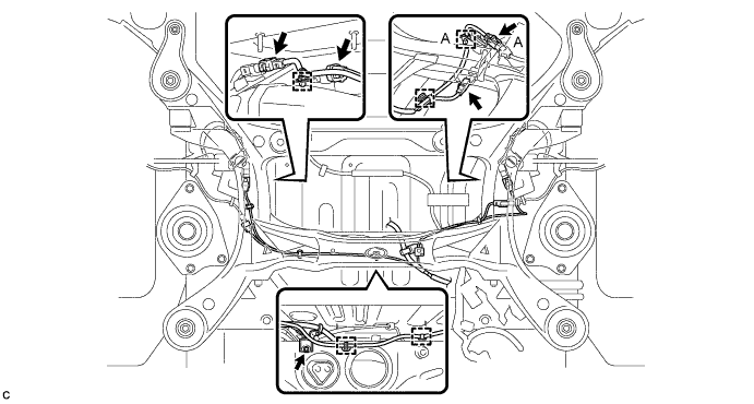
- Torque:
- 5.0 N*m { 51 kgf*cm, 44 in.*lbf }
Note
Do not twist the frame wire when installing it.
Tech Tips
There are only the connector (A) and the clamp (A) on vehicles with the air suspension.
-
-
TEMPORARILY TIGHTEN REAR DIFFERENTIAL CARRIER ASSEMBLY WITH DIFFERENTIAL SUPPORT
-
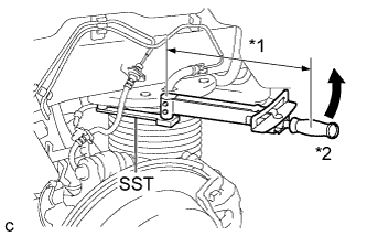
Text in Illustration *1 Attachment *2 Lower Rear Differential Mount Stopper Support the rear differential carrier assembly with differential support with a jack using 3 attachments as shown in the illustration.
-
Jack up the rear differential carrier assembly with differential support, temporarily install the rear differential carrier assembly with differential support to the front side of the rear suspension member assembly with the 2 lower rear differential mount stoppers, 2 new bolts and 2 new nuts.
Note
Be sure to install the lower rear differential mount stoppers with the convex side facing upward.
Tech Tips
The nuts have tabs to prevent them from rotating.
-
Temporarily install the rear differential carrier assembly with differential support and rear differential dynamic damper to the rear side of the rear suspension member assembly with the 2 new rear mounting bolts.
-
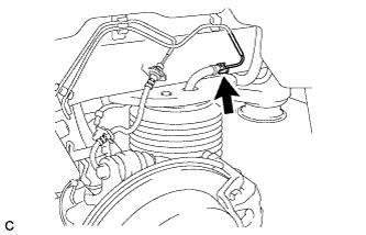
Text in Illustration *1 Vacuum Hose Connect the vacuum hose to the 2 clamps, connect the connector, and install the clamp to the connector bracket.
-
-
FULLY TIGHTEN REAR DIFFERENTIAL CARRIER ASSEMBLY WITH DIFFERENTIAL SUPPORT
Note
Do not tighten the bolts with the inner cylinder or rear differential mount cushion tilted.
-
Install the rear differential carrier assembly with differential support and rear differential dynamic damper to the rear side of the rear suspension member assembly with the 2 new rear mounting bolts.
- Torque:
- 95 N*m { 970 kgf*cm, 70 ft.*lbf }
-
Tighten the 2 new bolts.
- Torque:
- 86 N*m { 877 kgf*cm, 63 ft.*lbf }
Tech Tips
-
Tighten the bolts only if the No. 1 rear differential support has been removed from the rear differential carrier assembly.
-
Lower the jack to the extent that the bolts can still be tightened.
-
Tighten the rear differential carrier assembly with differential support to the front side of the rear suspension member assembly with the 2 new bolts.
- Torque:
- 80 N*m { 816 kgf*cm, 59 ft.*lbf }
-
Lower the jack.
-
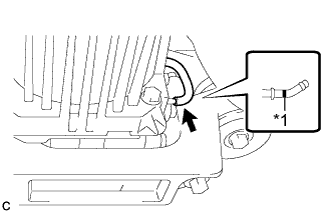
Text in Illustration *1 Paint Mark Connect the vacuum hose to the electro magnetic control coupling sub-assembly.
Note
Connect the vacuum hose until it reaches the paint mark.
-
-
INSTALL REAR DRIVE SHAFT SNAP RING LH
-
Install a new rear drive shaft snap ring.
-
-
INSTALL REAR DRIVE SHAFT SNAP RING RH
Tech Tips
Perform the same procedure as the LH side.
-
INSTALL REAR DRIVE SHAFT ASSEMBLY LH
-
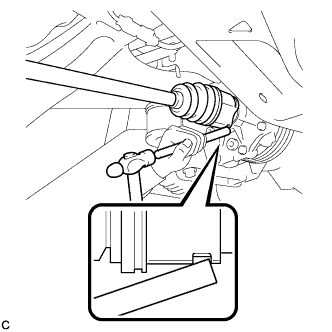
Align the shaft splines and install the rear drive shaft assembly with a brass bar and a hammer.
Note
-
Set the snap ring with the opening facing downward.
-
Be careful not to damage the oil seal, boot or dust cover.
-
Install the rear drive shaft assembly while keeping it level.
-
-
-
INSTALL REAR DRIVE SHAFT ASSEMBLY RH
Tech Tips
Perform the same procedure as the LH side.
-
TEMPORARILY TIGHTEN REAR AXLE CARRIER SUB-ASSEMBLY LH
-
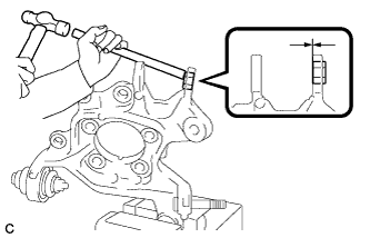
Hold the rear axle carrier sub-assembly LH between aluminum plates in a vise.
-
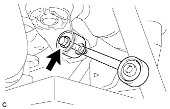
Using a brass bar and a hammer, push out the bushing until it is positioned as shown in the illustration.
Tech Tips
Pushing out the bushing makes it easier to install the rear axle carrier sub-assembly.
-
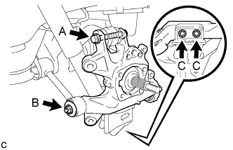
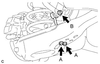
Temporarily tighten the rear axle carrier sub-assembly LH with the spacer, nut (B) and 2 bolts (C).
Note
-
Fully tighten the 2 bolts (C) after temporarily tightening the rear No. 2 suspension arm assembly.
-
Fully tighten the nut (B) after stabilizing the suspension.
-
Be careful not to damage the rear drive shaft outboard joint boot.
-
-
Fully tighten the rear axle carrier sub-assembly LH to the rear upper control arm assembly LH with the bolt (A) and nut.
- Torque:
- 145 N*m { 1479 kgf*cm, 107 ft.*lbf }
Note
-
Insert the bolt with the threaded end facing the rear side of the vehicle.
-
Since the stopper nut is used, tighten the bolt (A).
-
-
TEMPORARILY TIGHTEN REAR AXLE CARRIER SUB-ASSEMBLY RH
Tech Tips
Perform the same procedure as the LH side.
-
TEMPORARILY TIGHTEN PARKING BRAKE ASSEMBLY LH
-
Temporarily tighten the parking brake assembly to the rear axle carrier sub-assembly with the nut.
Note
-
Do not twist the parking brake cable when installing the parking brake assembly.
-
Fully tighten the nut after installing the rear trailing arm assembly.
-
-
-
TEMPORARILY TIGHTEN PARKING BRAKE ASSEMBLY RH
Tech Tips
Perform the same procedure as the LH side.
-
INSTALL REAR TRAILING ARM ASSEMBLY LH
-
Text in Illustration *1 Jack *2 Wooden Block Using a jack and wooden block, jack up the rear No. 2 suspension arm assembly to replicate standard vehicle height conditions.
CAUTION:
Do not jack up the rear No. 2 suspension arm assembly too high as the vehicle may fall.
-
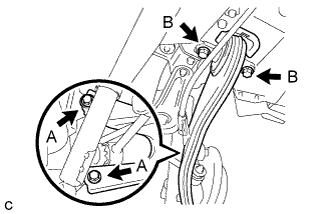
Install the rear trailing arm assembly to the rear axle carrier sub-assembly with the 2 bolts (A) and 2 washers.
- Torque:
- 150 N*m { 1530 kgf*cm, 111 ft.*lbf }
-
Install the rear trailing arm assembly to the body with the 2 bolts (B).
- Torque:
- 150 N*m { 1530 kgf*cm, 111 ft.*lbf }
-
Slowly lower the rear No. 2 suspension arm assembly.
-
Install the No. 3 parking brake cable assembly to the rear trailing arm assembly.
- Torque:
- 19 N*m { 192 kgf*cm, 14 ft.*lbf }
Note
Do not twist the No. 3 parking brake cable assembly when installing it.
-
-
INSTALL REAR TRAILING ARM ASSEMBLY RH
Tech Tips
Perform the same procedure as the LH side.
-
FULLY TIGHTEN PARKING BRAKE ASSEMBLY LH
-
Fully tighten the nut.
- Torque:
- 160 N*m { 1632 kgf*cm, 118 ft.*lbf }
-
-
FULLY TIGHTEN PARKING BRAKE ASSEMBLY RH
Tech Tips
Perform the same procedure as the LH side.
-
TEMPORARILY TIGHTEN REAR NO. 2 SUSPENSION ARM ASSEMBLY LH
w/o Air Suspension: Click here
w/ Air Suspension: Click here
-
TEMPORARILY TIGHTEN REAR NO. 2 SUSPENSION ARM ASSEMBLY RH
Tech Tips
Perform the same procedure as the LH side.
-
FULLY TIGHTEN REAR LOWER SHOCK ABSORBER BRACKET SUB-ASSEMBLY LH
-
Fully tighten the 2 bolts.
- Torque:
- 100 N*m { 1020 kgf*cm, 74 ft.*lbf }
-
-
FULLY TIGHTEN REAR LOWER SHOCK ABSORBER BRACKET SUB-ASSEMBLY RH
Tech Tips
Perform the same procedure as the LH side.
-
INSTALL REAR PNEUMATIC CYLINDER ABSORBER ASSEMBLY LH (w/ Air Suspension)
-
Install 2 new O-rings, a new plate, a new No. 2 connector to the rear pneumatic cylinder assembly.
Note
Perform this procedure when reusing the rear pneumatic cylinder assembly.
Tech Tips
For the installing procedure of the tube (type 2), refer to Precaution of Suspension Control System Click here.
-
Text in Illustration *1 Positioning Pin Install the rear pneumatic cylinder assembly to the rear No. 2 suspension arm assembly with the nut.
- Torque:
- 80 N*m { 816 kgf*cm, 59 ft.*lbf }
Note
When installing the rear spring set plate, first insert the positioning pin into the hole.
-
Text in Illustration *1 Jack *2 Wooden Block Jack up the rear axle assembly to install the rear pneumatic cylinder assembly, placing a wooden block underneath to avoid damage.
-
Temporarily install the rear pneumatic cylinder assembly to the body with the 3 bolts, and then fully tighten the 2 bolts (A).
- Torque:
- 50 N*m { 510 kgf*cm, 37 ft.*lbf }
-
Text in Illustration *1 Fulcrum Length *2 Turn Using SST and a socket wrench, fully tighten the bolt (B).
- SST
- 09961-00950
- Torque:
- without SST
- 50 N*m { 510 kgf*cm, 37 ft.*lbf }
- with SST
- 35 N*m { 355 kgf*cm, 26 ft.*lbf }
Note
-
Use a torque wrench with a fulcrum length of 345 mm (1.13 ft.).
-
This torque value is effective when SST is parallel to the torque wrench.
-
Slowly lower the rear axle assembly.
-
Connect the air tube to the rear pneumatic cylinder assembly.
Tech Tips
For the connecting procedure of the tube (type 2), refer to Precaution of Suspension Control System Click here.
-
-
INSTALL REAR PNEUMATIC CYLINDER ABSORBER ASSEMBLY RH (w/ Air Suspension)
Tech Tips
Perform the same procedure as the LH side.
-
INSTALL REAR STABILIZER LINK SUB-ASSEMBLY LH
-
Install the rear stabilizer link sub-assembly to the rear stabilizer bar with the nut (B).
- Torque:
- 90 N*m { 918 kgf*cm, 66 ft.*lbf }
Tech Tips
If the ball joint turns together with the nut (B), use a hexagon wrench (6 mm) to hold the stud bolt.
-
Install the rear stabilizer link sub-assembly to the rear No. 2 suspension arm assembly with the 2 nuts (A).
- Torque:
- 82 N*m { 836 kgf*cm, 60 ft.*lbf }
-
-
INSTALL REAR STABILIZER LINK SUB-ASSEMBLY RH
Tech Tips
Perform the same procedure as the LH side.
-
INSTALL REAR STABILIZER BAR
-
Type A:
-
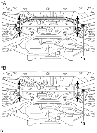
Text in Illustration *A Type A *B Type B *a Identification mark Install the rear stabilizer bar with 2 rear stabilizer bushings and rear No. 1 stabilizer bar bracket with the 4 nuts.
- Torque:
- 75 N*m { 765 kgf*cm, 55 ft.*lbf }
Note
Ensure that the identification mark faces the right side of the vehicle.
-
-
Type B:
-
Install the rear stabilizer bar with 2 rear stabilizer bushings and 2 rear No. 1 stabilizer bar brackets with the 4 nuts.
- Torque:
- 75 N*m { 765 kgf*cm, 55 ft.*lbf }
Note
Ensure that the identification mark faces the right side of the vehicle.
-
-
-
INSTALL REAR AXLE HUB AND BEARING ASSEMBLY LH
-
Text in Illustration *1 Matchmark Align the matchmarks on the rear drive shaft assembly and rear axle hub and bearing assembly, and then insert the rear drive shaft assembly to the rear axle hub and bearing assembly.
-
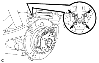
Install the rear axle hub and bearing assembly to the rear axle carrier sub-assembly with the 4 bolts.
- Torque:
- 125 N*m { 1275 kgf*cm, 92 ft.*lbf }
-
-
INSTALL REAR AXLE HUB AND BEARING ASSEMBLY RH
Tech Tips
Perform the same procedure as the LH side.
-
INSTALL REAR DISC LH
-
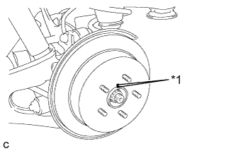
Text in Illustration *1 Matchmark Align the matchmarks and install the rear disc.
Note
When replacing the rear disc with a new one, select the installation position where the rear disc has minimal runout.
-
-
INSTALL REAR DISC RH
Tech Tips
Perform the same procedure as the LH side.
-
INSTALL PARKING BRAKE SHOE ADJUSTING HOLE PLUG (for LH Side)
-
Install the parking brake shoe adjusting hole plug.
-
-
INSTALL PARKING BRAKE SHOE ADJUSTING HOLE PLUG (for RH Side)
Tech Tips
Perform the same procedure as the LH side.
-
INSTALL REAR DISC BRAKE CALIPER ASSEMBLY LH
-
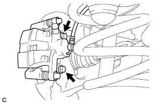
Install the rear disc brake caliper assembly to the rear axle carrier sub-assembly with the 2 bolts.
- Torque:
- 78 N*m { 799 kgf*cm, 58 ft.*lbf }
-
Install the rear flexible hose to the rear upper control arm assembly with the bolt.
- Torque:
- 19 N*m { 192 kgf*cm, 14 ft.*lbf }
Note
-
Do not twist the rear flexible hose when installing it.
-
Do not damage the rear flexible hose when reassembling it.
-
If the rear flexible hose is damaged, replace it with a new one.
-
Install the rear flexible hose to the bracket with a new clip.
Note
-
Install the clip as far as it will go.
-
Do not twist the rear flexible hose when installing it.
-
-
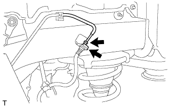
Using a union nut wrench, connect the brake line to the rear flexible hose.
- Torque:
- 15 N*m { 155 kgf*cm, 11 ft.*lbf }
Note
-
Do not bend or damage the brake line.
-
Do not allow any foreign matter such as dirt and dust to enter the brake line.
-
Use the formula to calculate special torque values for situations where the union nut wrench is combined with a torque wrench Click here.
-
-
INSTALL REAR DISC BRAKE CALIPER ASSEMBLY RH
Tech Tips
Perform the same procedure as the LH side.
-
INSTALL REAR AXLE SHAFT NUT LH
-
Clean the threaded parts on the rear drive shaft assembly and a new rear axle shaft nut using a non-residue solvent.
Note
-
Be sure to perform this work for a new rear drive shaft assembly.
-
Keep the threaded parts free of oil and foreign matter.
-
-
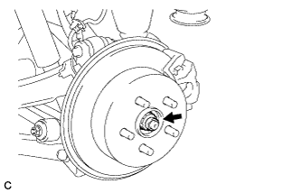
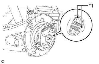
While applying the parking brakes, install the new rear axle shaft nut.
- Torque:
- 294 N*m { 2998 kgf*cm, 217 ft.*lbf }
-
Using a chisel and a hammer, stake the rear axle shaft nut.
-
-
INSTALL REAR AXLE SHAFT NUT RH
Tech Tips
Perform the same procedure as the LH side.
-
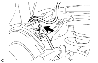
INSTALL REAR SPEED SENSOR LH
-
Install the rear speed sensor to the rear trailing arm assembly with the bolt.
- Torque:
- 8.0 N*m { 82 kgf*cm, 71 in.*lbf }
Note
Do not twist the rear speed sensor when installing it.
-
Install the rear speed sensor to the rear axle carrier sub-assembly with the bolt.
- Torque:
- 8.5 N*m { 87 kgf*cm, 75 in.*lbf }
Note
-
Prevent foreign matter from attaching to the rear speed sensor tip.
-
Do not file the rear speed sensor installation hole or surface because the gap between the magnet rotor and rear speed sensor is important.
-
Do not twist or apply excessive force to the rear speed sensor during installation to prevent it from being damaged.
-
Do not twist the rear speed sensor when installing it.
-
-
INSTALL REAR SPEED SENSOR RH
Tech Tips
Perform the same procedure as the LH side.
-
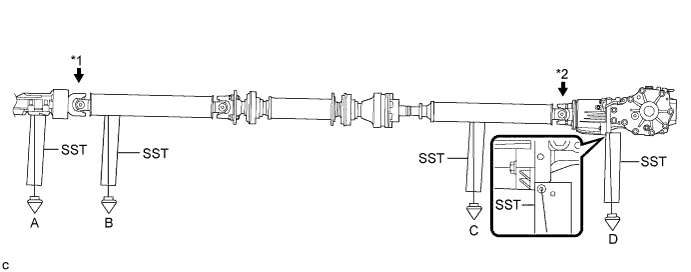
TEMPORARILY TIGHTEN PROPELLER WITH CENTER BEARING SHAFT ASSEMBLY
-
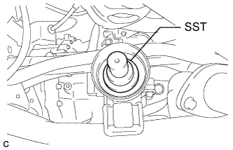
Remove SST from the transaxle.
-
Install the propeller with center bearing shaft assembly.
Note
-
Be careful not to damage the oil seal.
-
Be careful not to damage the universal joint boot when installing the propeller shaft.
-
-
Text in Illustration *1 Matchmark Align the matchmarks on the rear propeller shaft and the electromagnetic control coupling assembly and install the 4 nuts and 4 No. 2 center support bearing washers.
Note
Do not allow grease to adhere to the bolts or washers.
-
Temporarily install the propeller with center bearing shaft assembly with the 4 bolts, and 4 No. 2 center support bearing washers.
Note
-
Reuse the No. 2 center support bearing washers.
-
Do not allow grease to adhere to the bolts or washers.
-
-
Fully tighten the 4 nuts.
- Torque:
- 74 N*m { 750 kgf*cm, 54 ft.*lbf }
-
-
FULLY TIGHTEN PROPELLER WITH CENTER BEARING SHAFT ASSEMBLY
-
Depress the brake pedal and hold it.
-
Remove the piece of cloth or equivalent from the universal joint.
-
Using a hexagon wrench (6 mm), tighten the 6 bolts.
- Torque:
- 26 N*m { 265 kgf*cm, 19 ft.*lbf }
-
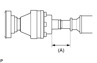
With the vehicle unloaded, adjust the dimension between the rear side of the cover and shaft as shown in the illustration.
Length (A) 65.5 to 70.5 mm (2.57 to 2.78 in.) -
With the vehicle unloaded, adjust the front and rear dimensions between the edge surface of the center support bearing and the edge surface of the cushion respectively as shown in the illustration, and then tighten the bolts.

Text in Illustration *1 No. 2 Center Support Bearing Assembly (for Front Side) *2 No. 2 Center Support Bearing Assembly (for Rear Side) Length (A) 11.5 to 13.5 mm (0.453 to 0.532 in.) -
Fully tighten the 4 bolts.
- Torque:
- 74 N*m { 750 kgf*cm, 54 ft.*lbf }
-
Check that the center line of the bracket is at a right angle to the shaft axial direction.
-
-
INSTALL TAIL EXHAUST PIPE ASSEMBLY
-
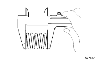
Using a vernier caliper, measure the free length of the compression springs.
Minimum length 38.5 mm (1.52 in.) If the free length is less than the minimum, replace the compression spring.
-
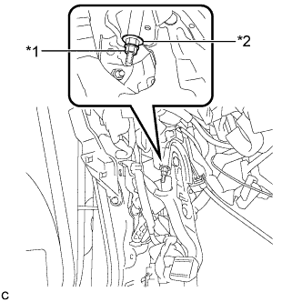
Fully insert a new gasket to the center exhaust pipe assembly.
-
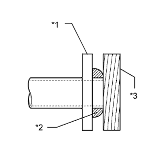
Text in Illustration *1 Center Exhaust Pipe Assembly *2 Gasket *3 Wooden Block Using a plastic hammer and wooden block, tap in the new gasket until its surface is flush with the center exhaust pipe assembly.
Note
-
Be sure to install the gasket in the correct direction.
-
Do not reuse the gasket.
-
Do not damage the gasket.
-
Do not push in the gasket by using the exhaust pipe when connecting it.
-
-
Connect the tail exhaust pipe assembly to the 4 exhaust pipe supports.
-
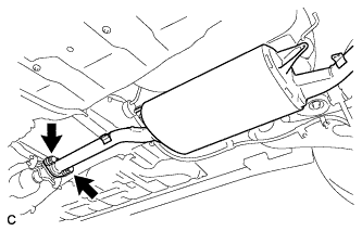
Install the tail exhaust pipe assembly with the 2 bolts and 2 compression springs.
- Torque:
- 43 N*m { 440 kgf*cm, 32 ft.*lbf }
-
-
STABILIZE SUSPENSION
-
Text in Illustration *1 Jack *2 Wooden Block Jack up the rear No. 2 suspension arm assembly, placing a wooden block underneath to avoid damage. Apply load to the suspension so that the rear upper control arm assembly is positioned as shown in the illustration.
Standard Length (A) 24.3 mm (0.957 in.) CAUTION:
Do not jack up the rear No. 2 suspension arm assembly too high as the vehicle may fall.
Tech Tips
-
If the rear upper control arm assembly cannot be positioned as shown in the illustration even when the rear No. 2 suspension arm assembly is jacked up, apply additional load such as by placing a weight in the luggage compartment.
-
Use the same procedure for the RH side and LH side.
-
-
-
FULLY TIGHTEN REAR NO. 1 SUSPENSION ARM ASSEMBLY LH
-
Using a ball joint lock nut wrench, fully tighten the bolt (B).
- Torque:
- 150 N*m { 1530 kgf*cm, 111 ft.*lbf }
Note
-
The final torque must be applied under standard vehicle height conditions.
-
Since the stopper nut is used, tighten the bolt (B).
-
Use the formula to calculate special torque values for situations where the ball joint lock nut wrench is combined with a torque wrench Click here.
-
Fully tighten the nut (A).
- Torque:
- 150 N*m { 1530 kgf*cm, 111 ft.*lbf }
Note
The final torque must be applied under standard vehicle height conditions.
-
-
FULLY TIGHTEN REAR NO. 1 SUSPENSION ARM ASSEMBLY RH
Tech Tips
Perform the same procedure as the LH side.
-
FULLY TIGHTEN REAR NO. 2 SUSPENSION ARM ASSEMBLY LH
-
Text in Illustration *1 Matchmark Align the matchmarks on the adjust cams and rear suspension member sub-assembly.
-
Fully tighten the nut.
- Torque:
- 100 N*m { 1020 kgf*cm, 74 ft.*lbf }
Note
-
The final torque must be applied under standard vehicle height conditions.
-
When tightening the nut, keep the toe adjust cam from rotating.
-
-
FULLY TIGHTEN REAR NO. 2 SUSPENSION ARM ASSEMBLY RH
Tech Tips
Perform the same procedure as the LH side.
-
INSTALL REAR SUSPENSION ARM COVER LH
w/o Air Suspension: Click here
w/ Air Suspension: Click here
-
INSTALL REAR SUSPENSION ARM COVER RH
Tech Tips
Perform the same procedure as the LH side.
-
ADJUST PARKING BRAKE SHOE CLEARANCE AND PARKING BRAKE PEDAL TRAVEL (for LHD)
-
Remove the No. 1 instrument panel under cover sub-assembly Click here.
-
Completely release the parking brake pedal.
-
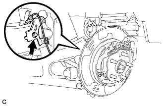
Text in Illustration *1 Lock Nut *2 Adjusting Nut Loosen the lock nut and the adjusting nut to completely release the parking brake cable.
-
Remove the rear wheels.
-
Temporarily install the hub nuts to the hub bolts.
Tech Tips
Securely install the hub nuts to the rear disc.
-
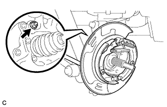
Remove the parking brake shoe adjusting hole plug Click here.
-
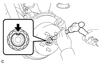
Text in Illustration *1 Expand *2 Contract Turn the shoe adjuster and expand the shoe until the disc locks.
-
Turn and contract the shoe adjuster until the disc can rotate smoothly.
Standard Return 8 notches. -
Check that there is no brake drag against the shoe.
-
Install the parking brake shoe adjusting hole plug Click here.
-
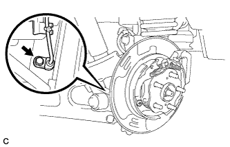
Turn the adjusting nut until the parking brake pedal travel is corrected to be within the specified range.
Parking brake pedal travel 7 to 10 notches at 300 N (31 kgf, 67.5 lbf) -
Text in Illustration *1 Lock Nut *2 Adjusting Nut Using a wrench or an equivalent tool, hold the adjusting nut and tighten the lock nut.
- Torque:
- 7.0 N*m { 71 kgf*cm, 62 in.*lbf }
-
Operate the parking brake pedal 3 to 4 times, and check the parking brake pedal travel.
-
Check that there is no brake drag against the shoe.
-
Remove the hub nuts from the hub bolts.
-
Install the rear wheels.
- Torque:
- 103 N*m { 1050 kgf*cm, 76 ft.*lbf }
-
Install the No. 1 instrument panel under cover sub-assembly Click here.
-
-
ADJUST PARKING BRAKE SHOE CLEARANCE AND PARKING BRAKE PEDAL TRAVEL (for RHD)
-
Remove the No. 1 instrument panel under cover sub-assembly Click here.
-
Completely release the parking brake pedal.
-
Text in Illustration *1 Lock Nut *2 Adjusting Nut Loosen the lock nut and the adjusting nut to completely release the parking brake cable.
-
Remove the rear wheels.
-
Temporarily install the hub nuts to the hub bolts.
Tech Tips
Securely install the hub nuts to the rear disc.
-
Remove the shoe adjusting hole plug Click here.
-
Text in Illustration *1 Expand *2 Contract Turn the shoe adjuster and expand the shoe until the disc locks.
-
Turn and contract the shoe adjuster until the disc can rotate smoothly.
Standard Return 8 notches. -
Check that there is no brake drag against the shoe.
-
Install the shoe adjusting hole plug Click here.
-
Turn the adjusting nut until the parking brake pedal travel is corrected to be within the specified range.
Parking brake pedal travel 7 to 10 notches at 300 N (31 kgf, 67.5 lbf) -
Text in Illustration *1 Lock Nut *2 Adjusting Nut Using a wrench or an equivalent tool, hold the adjusting nut and tighten the lock nut.
- Torque:
- 7.0 N*m { 71 kgf*cm, 62 in.*lbf }
-
Operate the parking brake pedal 3 to 4 times, and check the parking brake pedal travel.
-
Check that there is no brake drag against the shoe.
-
Remove the hub nuts from the hub bolts.
-
Install the rear wheels.
- Torque:
- 103 N*m { 1050 kgf*cm, 76 ft.*lbf }
-
Install the No. 1 instrument panel under cover sub-assembly Click here.
-
-
INSPECT AND ADJUST TRANSFER OIL
-
ADD DIFFERENTIAL OIL
-
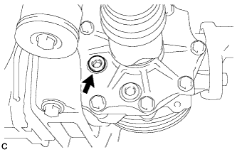
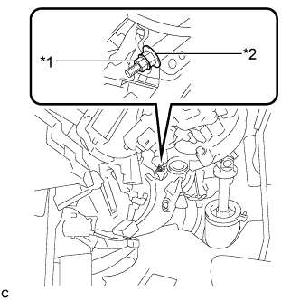
Using a hexagon wrench (10 mm), remove the differential inspection plug.
-
Add differential oil Click here.
-
-
INSPECT DIFFERENTIAL OIL
-
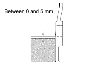
Check that the oil level is between 0 and 5 mm (0 and 0.197 in.) from the bottom lip of the differential inspection plug opening.
-
Inspect for oil leak if the oil level is low.
-
-
INSTALL DIFFERENTIAL INSPECTION PLUG
-
Using a hexagon wrench (10 mm), install the differential inspection plug and a new gasket.
- Torque:
- 39 N*m { 398 kgf*cm, 29 ft.*lbf }
-
-
CONNECT CABLE TO NEGATIVE BATTERY TERMINAL (w/ Air Suspension)
Note
When disconnecting the cable, some systems need to be initialized after the cable is reconnected Click here.
-
BLEED BRAKE SYSTEM
-
INSTALL REAR WHEELS
- Torque:
- 103 N*m { 1050 kgf*cm, 76 ft.*lbf }
-
INSPECT AND ADJUST JOINT ANGLE
-
If any vibration or noise occurs, perform joint angle check as follows and replace the No. 2 center support bearing washer with a proper one.
-
Turn the propeller shaft several times by hand to stabilize the center support bearings.
-
Using a jack, raise and lower the differential to stabilize the differential mounting cushion.
-
Remove the transfer dynamic damper.
Note
Measure the joint angle when the vehicle is raised using a four-post lift or when using a pit.
-
Using SST, measure the transfer installation angle (A) and front propeller shaft installation angle (B).
- SST
- 09370-50010
Text in Illustration *1 No. 1 Joint Angle *2 No. 4 Joint Angle No. 1 joint angle (A) - (B) = -3.02° to -1.02° -
Using SST, measure the rear propeller shaft installation angle (C) and rear differential shaft installation angle (D).
- SST
- 09370-50010
No. 4 joint angle (C) - (D) = 0.81° to 2.81° Tech Tips
If the calculated amount is not within the specification, adjust the joint angle with the No. 2 center support bearing washer.
Note
-
Make sure to use a washer of the same thickness on both right and left sides.
-
Do not use 2 or more washers on a bolt.
Center Support Bearing Adjusting Shim Thickness Thickness mm (in.) Thickness mm (in.) 3.2 (0.126) 11.0 (0.433) 4.5 (0.177) 13.5 (0.531) 6.5 (0.256) 15.5 (0.610) 9.0 (0.354) 17.5 (0.689) -
Install the transfer dynamic damper.
- Torque:
- 26 N*m { 260 kgf*cm, 19 ft.*lbf }
-
-
-
INSPECT FOR DIFFERENTIAL OIL LEAK
-
INSPECT FOR EXHAUST GAS LEAK
-
INSPECT FOR AIR LEAK (w/ Air Suspension)
-
CHECK VEHICLE HEIGHT (w/ Air Suspension)
Note
If the height control sensor link is removed, check the vehicle height.
-
Change the height control switch from the "NORM" position to the "HIGH" position and back to the "NORM" position.
-
Measure the vehicle height Click here.
-
-
ADJUST VEHICLE HEIGHT (w/ Air Suspension)
Note
If the height control sensor has been replaced, be sure to adjust the vehicle height.
-
Adjust the vehicle height Click here.
-
-
INSPECT AND ADJUST REAR WHEEL ALIGNMENT
-
HEIGHT CONTROL SENSOR SIGNAL INITIALIZATION (w/o Air Suspension)
-
INSPECT AND ADJUST HEADLIGHT AIMING