SFI SYSTEM Fuel Pump Control Circuit
DESCRIPTION
Refer to DTC P0230 Click here.
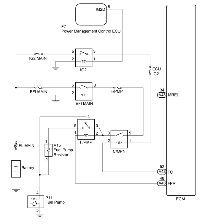
WIRING DIAGRAM
INSPECTION PROCEDURE
Note
Inspect the fuses for circuits related to this system before performing the following inspection procedure.
PROCEDURE
-
CHECK FUEL PUMP OPERATION
-
Check the fuel pump operation Click here.
NG 
PERFORM ACTIVE TEST USING INTELLIGENT TESTER (ACTIVATE THE FUEL PUMP SPEED CONTROL) Click here
OK 
-
-
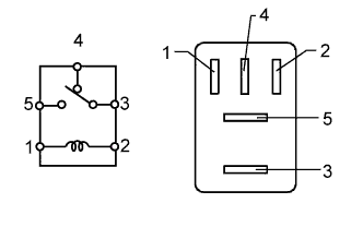
INSPECT RELAY (F/PMP RELAY)
-
Remove the F/PMP relay from the engine room relay block and junction block assembly.
-
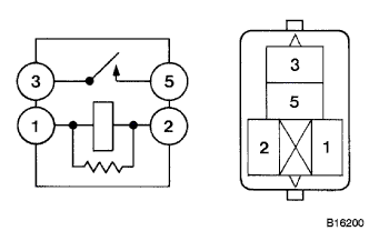
Measure the resistance according to the value(s) in the table below.
Standard Resistance Tester Connection Condition Specified Condition 3 - 4 No battery voltage applied across terminals 1 and 2 Below 1 Ω 3 - 4 Battery voltage applied across terminals 1 and 2 10 kΩ or higher 3 - 5 No battery voltage applied across terminals 1 and 2 10 kΩ or higher 3 - 5 Battery voltage applied across terminals 1 and 2 Below 1 Ω -
Reinstall the F/PMP relay.
NG 
REPLACE RELAY (F/PMP RELAY)
OK
-
-
INSPECT FUEL PUMP RESISTER
-
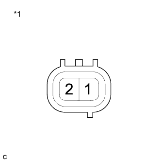
Text in Illustration *1 Component without harness connected
(Fuel Pump Resistor)
Disconnect the fuel pump resistor connector.
-
Measure the resistance according to the value(s) in the table below.
Standard Resistance Tester Connection Condition Specified Condition 1 - 2 20°C (68°F) 0.30 to 0.34 Ω -
Reconnect the fuel pump resistor connector.
NG
REPLACE FUEL PUMP RESISTER Click here
OK
-
-
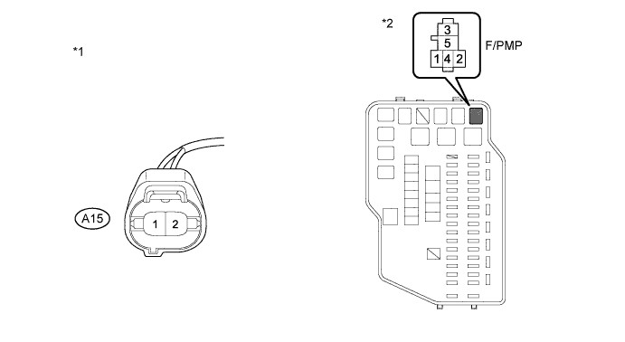
CHECK HARNESS AND CONNECTOR (F/PMP RELAY - FUEL PUMP RESISTOR)
-
Remove the F/PMP relay from the engine room relay block and junction block assembly.
-
Disconnect the fuel pump resistor connector.
-
Measure the resistance according to the value(s) in the table below.
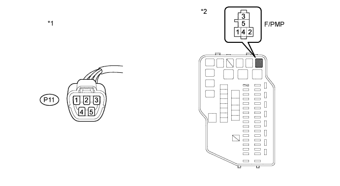
Standard Resistance (Check for Open) Tester Connection Condition Specified Condition 5 (F/PMP relay terminal) - A15-1 Always Below 1 Ω 4 (F/PMP relay terminal) - A15-2 Always Below 1 Ω Standard Resistance (Check for Short) Tester Connection Condition Specified Condition 5 (Fuel pump relay terminal) or A15-1 - Body ground Always 10 kΩ or higher 4 (Fuel pump relay terminal) or A15-2 - Body ground Always 10 kΩ or higher Text in Illustration *1 Front view of wire harness connector
(to Fuel Pump Resistor)
*2 Engine Room Relay Block and Junction Block Assembly -
Reinstall the F/PMP relay.
-
Reconnect the fuel pump resistor connector.
NG
REPAIR OR REPLACE HARNESS OR CONNECTOR (F/PMP RELAY - FUEL PUMP RESISTOR)
OK 
PROCEED TO NEXT SUSPECTED AREA SHOWN IN PROBLEM SYMPTOMS TABLE Click here
-
-
PERFORM ACTIVE TEST USING INTELLIGENT TESTER (ACTIVATE THE FUEL PUMP SPEED CONTROL)
-
Connect the intelligent tester to the DLC3.
-
Turn the engine switch on (IG) and turn the tester on.
-
Enter the following menus: Powertrain / Engine / Active Test / Activate the Fuel Pump Speed Control.
-
Check the operation of the relay while operating it using the tester.
OK Operating noise can be heard from the relay.
NG
INSPECT RELAY (C/OPN RELAY) Click here
OK
-
-
INSPECT FUEL PUMP
-
Inspect the fuel pump Click here.
NG
REPLACE FUEL PUMP Click here
OK
-
-
CHECK HARNESS AND CONNECTOR (FUEL PUMP - F/PMP RELAY)
-
Disconnect the fuel pump connector.
-
Remove the F/PMP relay from the engine room relay block and junction block assembly.
-
Measure the resistance according to the value(s) in the table below.
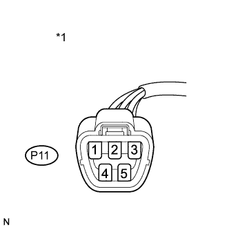
Standard Resistance (Check for Open) Tester Connection Condition Specified Condition P11-4 - 4 (F/PMP relay terminal) Always Below 1 Ω Standard Resistance (Check for Short) Tester Connection Condition Specified Condition P11-4 or 4 (F/PMP relay terminal) - Body ground Always 10 kΩ or higher Text in Illustration *1 Front view of wire harness connector
(to Fuel Pump)
*2 Engine Room Relay Block and Junction Block Assembly -
Reinstall the F/PMP relay.
-
Reconnect the fuel pump connector.
NG
REPAIR OR REPLACE HARNESS OR CONNECTOR (FUEL PUMP - F/PMP RELAY)
OK
-
-
INSPECT ENGINE ROOM RELAY BLOCK AND JUNCTION BLOCK ASSEMBLY (C/OPN RELAY - F/PMP RELAY)
-
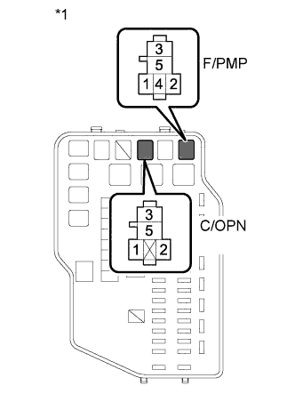
Text in Illustration *1 Engine Room Relay Block and Junction Block Assembly Remove the C/OPN relay from the engine room relay block and junction block assembly.
-
Remove the F/PMP relay from the engine room relay block and junction block assembly.
-
Measure the resistance according to the value(s) in the table below.
Standard Resistance (Check for Open) Tester Connection Condition Specified Condition 3 (C/OPN relay terminal) - 2 (F/PMP relay terminal) Always Below 1 Ω 3 (C/OPN relay terminal) - 3 (F/PMP relay terminal) Always Below 1 Ω Standard Resistance (Check for Short) Tester Connection Condition Specified Condition 3 (C/OPN relay terminal) or 2 (F/PMP relay terminal) - Body ground Always 10 kΩ or higher 3 (C/OPN relay terminal) or 3 (F/PMP relay terminal) - Body ground Always 10 kΩ or higher -
Reinstall the C/OPN relay.
-
Reinstall the F/PMP relay.
NG
REPLACE ENGINE ROOM RELAY BLOCK AND JUNCTION BLOCK ASSEMBLY
OK
-
-
CHECK HARNESS AND CONNECTOR (FUEL PUMP - BODY GROUND)
-
Text in Illustration *1 Front view of wire harness connector
(to Fuel Pump)
Disconnect the fuel pump connector.
-
Measure the resistance according to the value(s) in the table below.
Standard Resistance (Check for Open) Tester Connection Condition Specified Condition P11-5 - Body ground Always Below 1 Ω -
Reconnect the fuel pump connector.
NG
REPAIR OR REPLACE HARNESS OR CONNECTOR (FUEL PUMP - BODY GROUND)
OK
-
-
CHECK FUEL LINE
-
Check the fuel lines for leaks or blockage.
OK No leaks or blockage
NG
REPAIR OR REPLACE FUEL LINE
OK
REPAIR OR REPLACE FUEL SYSTEM (PRESSURE REGULATOR AND FUEL FILTER)
-
-
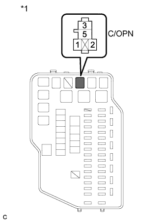
INSPECT RELAY (C/OPN RELAY)
-
Remove the C/OPN relay from the engine room relay block and junction block assembly.
-
Measure the resistance according to the value(s) in the table below.
Standard Resistance Tester Connection Condition Specified Condition 3 - 5 No battery voltage applied across terminals 1 and 2 10 kΩ or higher 3 - 5 Battery voltage applied across terminals 1 and 2 Below 1 Ω -
Reinstall the C/OPN relay.
NG
REPLACE RELAY (C/OPN RELAY)
OK
-
-
CHECK HARNESS AND CONNECTOR (C/OPN RELAY VOLTAGE)
-
Text in Illustration *1 Engine Room Relay Block and Junction Block Assembly Remove the C/OPN relay from the engine room relay block and junction block assembly.
-
Turn the engine switch on (IG).
-
Measure the voltage according to the value(s) in the table below.
Standard Voltage Tester Connection Condition Specified Condition 5 (C/OPN relay terminal) - Body ground Engine switch on (IG) 11 to 14 V 1 (C/OPN relay terminal) - Body ground Engine switch on (IG) 11 to 14 V -
Reinstall the C/OPN relay.
NG
REPLACE ENGINE ROOM RELAY BLOCK AND JUNCTION BLOCK ASSEMBLY
OK
-
-
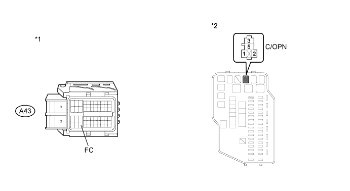
CHECK HARNESS AND CONNECTOR (C/OPN RELAY - ECM)
-
Remove the C/OPN relay from the engine room relay block and junction block assembly.
-
Disconnect the ECM connector.
-
Measure the resistance according to the value(s) in the table below.
Standard Resistance (Check for Open) Tester Connection Condition Specified Condition 2 (C/OPN relay terminal) - A43-52 (FC) Always Below 1 Ω Standard Resistance (Check for Short) Tester Connection Condition Specified Condition 2 (C/OPN relay terminal) or A43-52 (FC) - Body ground Always 10 kΩ or higher Text in Illustration *1 Front view of wire harness connector
(to ECM)
*2 Engine Room Relay Block and Junction Block Assembly -
Reconnect the ECM connector.
-
Reinstall the C/OPN relay.
NG
REPAIR OR REPLACE HARNESS OR CONNECTOR (C/OPN RELAY - ECM)
OK
REPLACE ECM Click here
-