SFI SYSTEM, Diagnostic DTC:P0724

| DTC Code | DTC Name |
|---|---|
| P0724 | Brake Switch "B" Circuit High |
DESCRIPTION
The stop light switch assembly is part of a duplex system that transmits two signals: STP and ST1-. These two signals are used by the ECM to monitor whether or not the brake system is working properly. This DTC indicates that the stop light switch assembly remains on. When the stop light switch assembly remains on during STOP and GO driving, the ECM interprets this as a fault in the stop light switch assembly. Then the ECM illuminates the MIL and the ECM stores the DTC.
| DTC No. | DTC Detection Condition | Trouble Area |
|---|---|---|
| P0724 | The stop light switch assembly remains on even when the vehicle repeats 5 cycles of STOP (less than 3 km/h [1.86 mph]) and GO (30 km/h [18.65 mph] or more) (2 trip detection logic). |
|
WIRING DIAGRAM
Refer to DTC P0504 Click here.
INSPECTION PROCEDURE
Note
Inspect the fuses for circuits related to this system before performing the following inspection procedure.
Tech Tips
-
Read freeze frame data using the intelligent tester. The ECM records vehicle and driving condition information as freeze frame data the moment a DTC is stored. When troubleshooting, freeze frame data can help determine if the vehicle was moving or stationary, if the engine was warmed up or not, if the air fuel ratio was lean or rich, and other data from the time the malfunction occurred.
-
Using the intelligent tester, the Data List item "Stop Light Switch" and "ST1" can be read Click here.
PROCEDURE
-
READ VALUE USING INTELLIGENT TESTER (STOP LIGHT SWITCH)
-
Connect the intelligent tester to the DLC3.
-
Turn the engine switch on (IG).
-
Turn the tester on.
-
Enter the following menus: Powertrain / Engine / Data List / All Data / Stop Light Switch.
-
Read the values displayed on the tester.
OK Tester Display Measurement Item/Range (Display) Normal Condition Stop Light Switch Stop light switch assembly status:
ON or OFF
-
ON: Brake pedal depressed
-
OFF: Brake pedal released
-
NG 
INSPECT STOP LIGHT SWITCH ASSEMBLY Click here
OK 
CHECK FOR INTERMITTENT PROBLEMS Click here
-
-
INSPECT STOP LIGHT SWITCH ASSEMBLY
-
Inspect the stop light switch assembly Click here.
NG 
REPLACE STOP LIGHT SWITCH ASSEMBLY Click here
OK 
-
-
CHECK HARNESS AND CONNECTOR (STP VOLTAGE)
-
Disconnect the ECM connector.
-
Measure the voltage according to the value(s) in the table below.
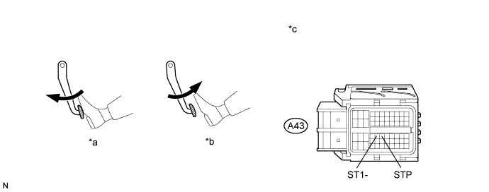
Standard Voltage Tester Connection Condition Specified Condition A43-36 (STP) - Body ground Brake pedal released Below 1.5 V Brake pedal depressed 7.5 to 14 V Text in Illustration *a Brake Pedal Depressed *b Brake Pedal Released *c Front view of wire harness connector
(to ECM)
- - -
Reconnect the ECM connector.
NG
REPAIR OR REPLACE HARNESS OR CONNECTOR (STOP LIGHT SWITCH ASSEMBLY - ECM)
OK
REPLACE ECM Click here
-