SFI SYSTEM, Diagnostic DTC:P0031, P0032, P0051, P0052, P101D, P103D

| DTC Code | DTC Name |
|---|---|
| P0031 | Oxygen (A/F) Sensor Heater Control Circuit Low (Bank 1 Sensor 1) |
| P0032 | Oxygen (A/F) Sensor Heater Control Circuit High (Bank 1 Sensor 1) |
| P0051 | Oxygen (A/F) Sensor Heater Control Circuit Low (Bank 2 Sensor 1) |
| P0052 | Oxygen (A/F) Sensor Heater Control Circuit High (Bank 2 Sensor 1) |
| P101D | A/F Sensor Heater Circuit Performance Bank 1 Sensor 1 Stuck ON |
| P103D | A/F Sensor Heater Circuit Performance Bank 2 Sensor 1 Stuck ON |
DESCRIPTION
Refer to DTC P2195 Click here.
Tech Tips
-
When any of these DTCs are set, the ECM enters fail-safe mode. The ECM turns off the air fuel ratio sensor heater in fail-safe mode. Fail-safe mode continues until the engine switch is turned off.
-
Although the DTC titles include oxygen sensor, these DTCs relate to the air fuel ratio sensor.
-
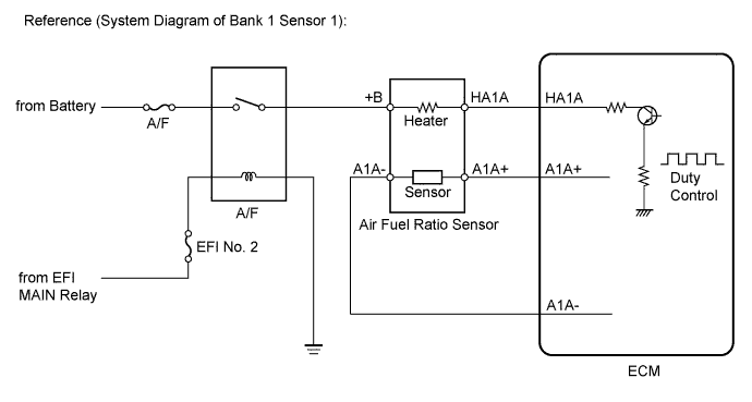
The ECM provides a pulse width modulated control circuit to adjust the current through the heater. The air fuel ratio sensor heater circuit uses a relay on the +B side of the circuit.
| DTC No. | DTC Detection Condition | Trouble Area |
|---|---|---|
| P0031 P0051 |
Air fuel ratio sensor heater (bank 1, 2 sensor 1) current less than 0.8 A (1 trip detection logic) |
|
| P0032 P0052 |
Air fuel ratio sensor heater (bank 1, 2 sensor 1) current fail (1 trip detection logic) |
|
| P101D P103D |
Air fuel ratio sensor heater current is higher than the specified value while the heater is not operating (1 trip detection logic) |
ECM |
WIRING DIAGRAM
Refer to DTC P2195 Click here.
INSPECTION PROCEDURE
Note
Inspect the fuses for circuits related to this system before performing the following inspection procedure.
Tech Tips
-
Refer to "Data List / Active Test" [A/F Heater Duty #1 and A/F Heater Duty #2] Click here.
-
Read freeze frame data using the intelligent tester. The ECM records vehicle and driving condition information as freeze frame data the moment a DTC is stored. When troubleshooting, freeze frame data can help determine if the vehicle was moving or stationary, if the engine was warmed up or not, if the air fuel ratio was lean or rich, and other data from the time the malfunction occurred.
-
Bank 1 refers to the bank that includes cylinder No. 1.
-
Bank 2 refers to the bank that does not include cylinder No. 1.
-
Sensor 1 refers to the sensor closest to the engine assembly.
-
Sensor 2 refers to the sensor farthest away from the engine assembly.
-
Change the fuel injection volume using the Control the Injection Volume function provided in the Active Test and monitor the air fuel ratio sensor output voltage Click here. If the sensor output voltage does not change (almost no reaction) while performing the Active Test, the sensor may be malfunctioning.
PROCEDURE
-
INSPECT AIR FUEL RATIO SENSOR (HEATER RESISTANCE)
-
Inspect the air fuel ratio sensor Click here.
NG 
REPLACE AIR FUEL RATIO SENSOR Click here
OK 
-
-
CHECK TERMINAL VOLTAGE (POWER SOURCE OF AIR FUEL RATIO SENSOR)
-
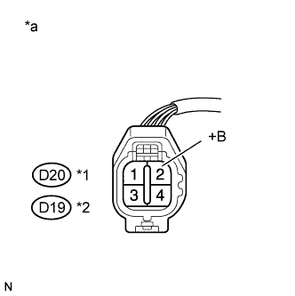
Text in Illustration *1 Bank 1 *2 Bank 2 *a Front view of wire harness connector
(to Air Fuel Ratio Sensor)
Disconnect the air fuel ratio sensor connector.
-
Turn the engine switch on (IG).
-
Measure the voltage according to the value(s) in the table below.
Standard Voltage Tester Connection Condition Specified Condition D20-2 (+B) - Body ground Engine switch on (IG) 11 to 14 V D19-2 (+B) - Body ground Engine switch on (IG) 11 to 14 V -
Reconnect the air fuel ratio sensor connector.
NG 
CHECK HARNESS AND CONNECTOR (AIR FUEL RATIO SENSOR - ENGINE ROOM RELAY BLOCK AND JUNCTION BLOCK ASSEMBLY) Click here
OK
-
-
CHECK HARNESS AND CONNECTOR (AIR FUEL RATIO SENSOR - ECM)
-
Disconnect the air fuel ratio sensor connector.
-
Disconnect the ECM connector.
-
Measure the resistance according to the value(s) in the table below.
Standard Resistance (Check for Open) Tester Connection Condition Specified Condition D20-1 (HA1A) - D1-22 (HA1A) Always Below 1 Ω D19-1 (HA2A) - D1-20 (HA2A) Always Below 1 Ω Standard Resistance (Check for Short) Tester Connection Condition Specified Condition D20-1 (HA1A) or D1-22 (HA1A) - Body ground Always 10 kΩ or higher D19-1 (HA2A) or D1-20 (HA2A) - Body ground Always 10 kΩ or higher -
Reconnect the air fuel ratio sensor connector.
-
Reconnect the ECM connector.
NG
REPAIR OR REPLACE HARNESS OR CONNECTOR (AIR FUEL RATIO SENSOR - ECM)
OK
-
-
CHECK WHETHER DTC OUTPUT RECURS (DTC P0031, P0032, P0051, P0052, P101D OR P103D)
-
Connect the intelligent tester to the DLC3.
-
Turn the engine switch on (IG).
-
Turn the tester on.
-
Clear the DTCs Click here.
-
Start the engine and idle it for 5 minutes or more.
-
With the vehicle stationary, depress the accelerator pedal and maintain an engine speed of 3000 rpm for 1 minute.
-
Idle the engine for 5 minutes or more.
-
Enter the following menus: Powertrain / Engine / DTC.
-
Read the DTCs.
Result Result Proceed to DTC is not output A DTC P0031, P0032, P0051, P0052, P101D or P103D is output B
B
REPLACE ECM Click here
A 
CHECK FOR INTERMITTENT PROBLEMS Click here
-
-
CHECK HARNESS AND CONNECTOR (AIR FUEL RATIO SENSOR - ENGINE ROOM RELAY BLOCK AND JUNCTION BLOCK ASSEMBLY)
-
Disconnect the air fuel ratio sensor connector.
-
Remove the engine room relay block and junction block assembly.
-
Disconnect the engine room relay block and junction block assembly connector.
-
Measure the resistance according to the value(s) in the table below.
Standard Resistance (Check for Open) Tester Connection Condition Specified Condition D20-2 (+B) - 3C-2 (Engine room relay block and junction block assembly) Always Below 1 Ω D19-2 (+B) - 3C-2 (Engine room relay block and junction block assembly) Always Below 1 Ω Standard Resistance (Check for Short) Tester Connection Condition Specified Condition D20-2 (+B) or 3C-2 (Engine room relay block and junction block assembly) - Body ground Always 10 kΩ or higher D19-2 (+B) or 3C-2 (Engine room relay block and junction block assembly) - Body ground Always 10 kΩ or higher -
Reconnect the engine room relay block and junction block assembly connector.
-
Reinstall the engine room relay block and junction block assembly.
-
Reconnect the air fuel ratio sensor connector.
NG
REPAIR OR REPLACE HARNESS OR CONNECTOR (AIR FUEL RATIO SENSOR - ENGINE ROOM RELAY BLOCK AND JUNCTION BLOCK ASSEMBLY)
OK
-
-
CHECK TERMINAL VOLTAGE (POWER SOURCE OF A/F RELAY)
-
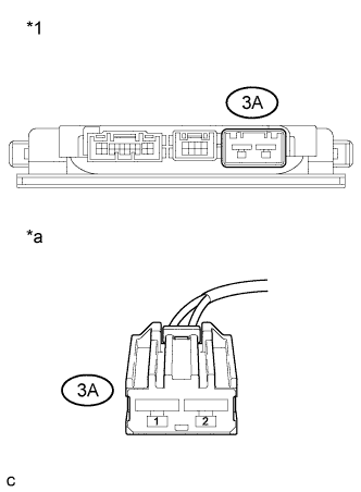
Text in Illustration *1 Engine Room Relay Block and Junction Block Assembly *a Front view of wire harness connector
(to Engine Room Relay Block and Junction Block Assembly)
Remove the engine room relay block and junction block assembly.
-
Disconnect the engine room relay block and junction block assembly connector.
-
Measure the voltage according to the value(s) in the table below.
Standard Voltage Tester Connection Condition Specified Condition 3A-1 (Engine room relay block and junction block assembly) - Body ground Always 11 to 14 V -
Reconnect the engine room relay block and junction block assembly connector.
-
Reinstall the engine room relay block and junction block assembly.
NG
REPAIR OR REPLACE HARNESS OR CONNECTOR (ENGINE ROOM RELAY BLOCK AND JUNCTION BLOCK ASSEMBLY - BATTERY)
OK
-
-
CHECK HARNESS AND CONNECTOR (ENGINE ROOM RELAY BLOCK AND JUNCTION BLOCK ASSEMBLY - EFI MAIN RELAY)
-
Remove the engine room relay block and junction block assembly.
-
Disconnect the engine room relay block and junction block assembly connector.
-
Remove the EFI MAIN relay from the engine room relay block and junction block assembly.
-
Measure the resistance according to the value(s) in the table below.
Standard Resistance (Check for Open) Tester Connection Condition Specified Condition 3C-7 (Engine room relay block and junction block assembly) - EFI MAIN relay terminal 3 Always Below 1 Ω Standard Resistance (Check for Short) Tester Connection Condition Specified Condition 3C-7 (Engine room relay block and junction block assembly) or EFI MAIN relay terminal 3 - Body ground Always 10 kΩ or higher -
Reinstall the EFI MAIN relay.
-
Reconnect the engine room relay block and junction block assembly connector.
-
Reinstall the engine room relay block and junction block assembly.
NG
REPAIR OR REPLACE HARNESS OR CONNECTOR (ENGINE ROOM RELAY BLOCK AND JUNCTION BLOCK ASSEMBLY - EFI MAIN RELAY)
OK
-
-
CHECK HARNESS AND CONNECTOR (ENGINE ROOM RELAY BLOCK AND JUNCTION BLOCK ASSEMBLY - BODY GROUND)
-
Remove the engine room relay block and junction block assembly.
-
Disconnect the engine room relay block and junction block assembly connector.
-
Measure the resistance according to the value(s) in the table below.
Standard Resistance (Check for Open) Tester Connection Condition Specified Condition 3C-17 (Engine room relay block and junction block assembly) - Body ground Always Below 1 Ω -
Reconnect the engine room relay block and junction block assembly connector.
-
Reinstall the engine room relay block and junction block assembly.
NG
REPAIR OR REPLACE HARNESS OR CONNECTOR (ENGINE ROOM RELAY BLOCK AND JUNCTION BLOCK ASSEMBLY - BODY GROUND)
OK
REPLACE ENGINE ROOM RELAY BLOCK AND JUNCTION BLOCK ASSEMBLY Click here
-