SFI SYSTEM, Diagnostic DTC:P0230

| DTC Code | DTC Name |
|---|---|
| P0230 | Fuel Pump Primary Circuit |
DESCRIPTION
-
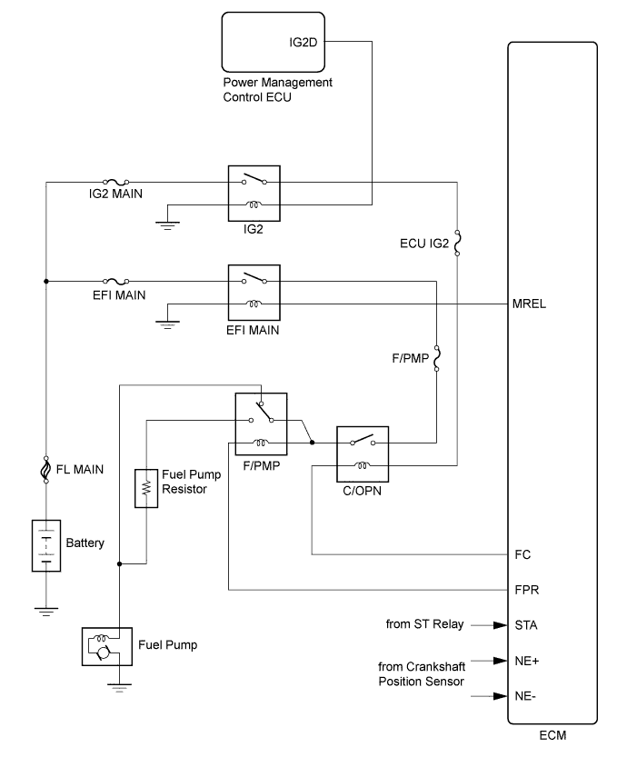
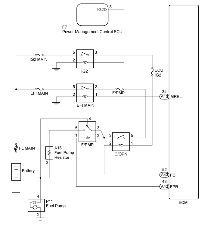
This DTC is designed to detect a malfunction in the F/PMP relay circuit. When the system is normal, battery voltage is applied to the FPR terminal of the ECM while the F/PMP relay is off. If battery voltage is not applied to the FPR terminal while the F/PMP relay is off, the ECM interprets this as a malfunction.
-
The F/PMP relay switches the fuel pump speed according to the engine conditions. The fuel pump operates when the ECM receives the STA signal and NE signal. The F/PMP relay is turned on while the engine is idling or operating at low load. This causes current to flow through the fuel pump resistor to the fuel pump. The fuel pump then operates at low speed. The F/PMP relay is turned off while the engine is cranking or operating at high load. The fuel pump then operates at normal speed.
| DTC No. | DTC Detection Condition | Trouble Area |
|---|---|---|
| P0230 | Open or short in F/PMP relay circuit (1 trip detection logic) |
|
WIRING DIAGRAM
INSPECTION PROCEDURE
Tech Tips
Read freeze frame data using the intelligent tester. The ECM records vehicle and driving condition information as freeze frame data the moment a DTC is stored. When troubleshooting, freeze frame data can help determine if the vehicle was moving or stationary, if the engine was warmed up or not, if the air fuel ratio was lean or rich, and other data from the time the malfunction occurred.
PROCEDURE
-
INSPECT F/PMP RELAY
-
Remove the F/PMP relay from the engine room relay block and junction block assembly.
-
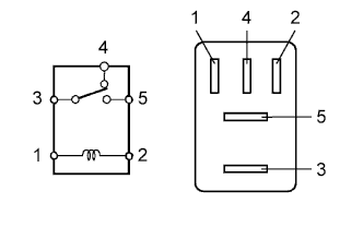
Measure the resistance according to the value(s) in the table below.
Standard Resistance Tester Connection Condition Specified Condition 3 - 4 No battery voltage applied across terminals 1 and 2 Below 1 Ω 3 - 4 Battery voltage applied across terminals 1 and 2 10 kΩ or higher 3 - 5 No battery voltage applied across terminals 1 and 2 10 kΩ or higher 3 - 5 Battery voltage applied across terminals 1 and 2 Below 1 Ω -
Reinstall the F/PMP relay.
NG 
REPLACE F/PMP RELAY
OK 
-
-
CHECK TERMINAL VOLTAGE (F/PMP RELAY)
-
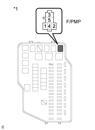
Text in Illustration *1 Engine Room Relay Block and Junction Block Assembly Remove the F/PMP relay from the engine room relay block and junction block assembly.
-
Measure the voltage according to the value(s) in the table below.
Standard Voltage Tester Connection Condition Specified Condition F/PMP relay terminal 2 - Body ground Cranking 11 to 14 V F/PMP relay terminal 2 - Body ground Engine switch on (IG) 0 to 3 V -
Reinstall the F/PMP relay.
NG
CHECK FUEL PUMP CONTROL CIRCUIT Click here
OK
-
-
CHECK HARNESS AND CONNECTOR (F/PMP RELAY - ECM)
-
Remove the F/PMP relay from the engine room relay block and junction block assembly.
-
Disconnect the ECM connector.
-
Measure the resistance according to the value(s) in the table below.
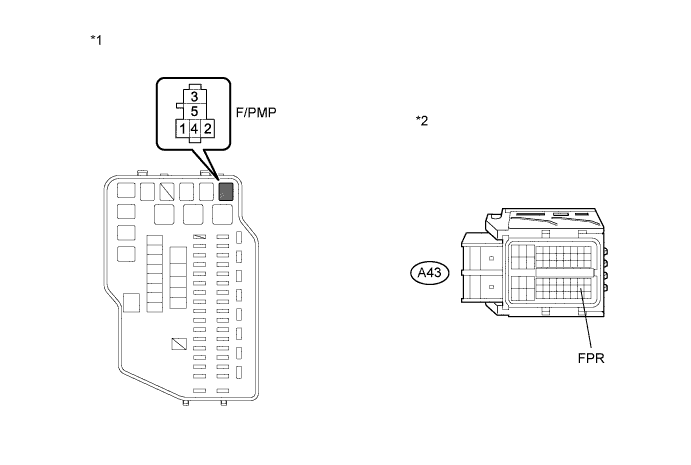
Standard Resistance (Check for Open) Tester Connection Condition Specified Condition F/PMP relay terminal 1 - A43-48 (FPR) Always Below 1 Ω Standard Resistance (Check for Short) Tester Connection Condition Specified Condition F/PMP relay terminal 1 or A43-48 (FPR) - Body ground Always 10 kΩ or higher Text in Illustration *1 Engine Room Relay Block and Junction Block Assembly *2 Front view of wire harness connector
(to ECM)
-
Reconnect the ECM connector.
-
Reinstall the F/PMP relay.
NG
REPAIR OR REPLACE HARNESS OR CONNECTOR (F/PMP RELAY - ECM)
OK 
REPLACE ECM Click here
-