МАСЛЯНЫЙ НАСОС УСТАНОВКА

-
INSTALL TIMING CHAIN COVER ASSEMBLY
-
Remove any old packing (FIPG material) and be careful not to drop any oil on the contact surfaces of the timing chain cover assembly, camshaft housing sub-assembly, stiffening crankcase assembly, cylinder block sub-assembly and cylinder head sub-assembly.
Note
Be sure to clean and degrease the contact surfaces, especially the surfaces indicated in the illustration.
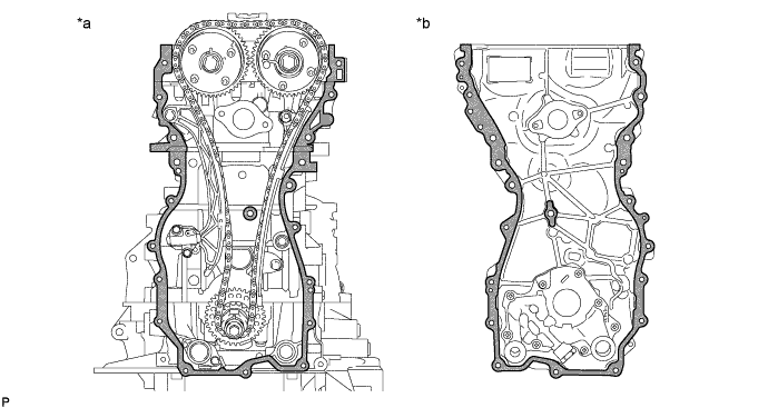
Text in Illustration *a Engine Side *b Timing Chain Cover Assembly Side 
Clean and degrease - - -
Apply a light coat of engine oil to 2 new gaskets.
-
Install the 2 gaskets to the stiffening crankcase assembly and oil strainer sub-assembly.
-
Install a water outlet gasket to the cylinder head sub-assembly.
-
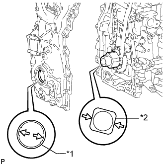
Text in Illustration *1 Oil Pump Drive Rotor Spline *2 Crankshaft Timing Sprocket Align the oil pump drive rotor spline and crankshaft timing sprocket as shown in the illustration.
-
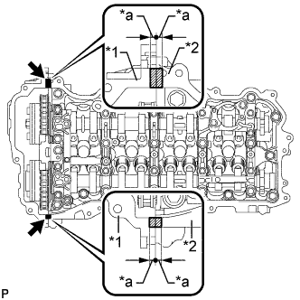
Apply seal packing as shown in the illustration.
Seal packing Toyota Genuine Seal Packing Black, Three Bond 1207B or equivalent Note
-
Install the timing chain cover assembly within 3 minutes and tighten the bolts and nuts within 10 minutes after applying seal packing.
-
Do not add engine oil within 2 hours of installation.
-
Do not start the engine for at least 2 hours after the installation.
Application Specification Area Seal Packing Diameter Seal Packing Width Seal Packing Height Application Position from Inside Seal Line Dashed line area 3.0 mm (0.118 in.) - - 2.5 mm (0.0984 in.) A - A 3.0 mm (0.118 in.) - - 2.5 mm (0.0984 in.) B - B 5.0 mm (0.197 in.) 7.0 mm (0.276 in.) or more 3.0 mm (0.118 in.) or more 3.0 mm (0.118 in.) C - C 7.0 mm (0.276 in.) 13 mm (0.512 in.) or more 3.0 mm (0.118 in.) or more 5.0 mm (0.197 in.) D - D 5.0 mm (0.197 in.) 7.0 mm (0.276 in.) or more 3.0 mm (0.118 in.) or more 3.0 mm (0.118 in.) E 3.0 mm (0.118 in.) - - 3.0 mm (0.118 in.) 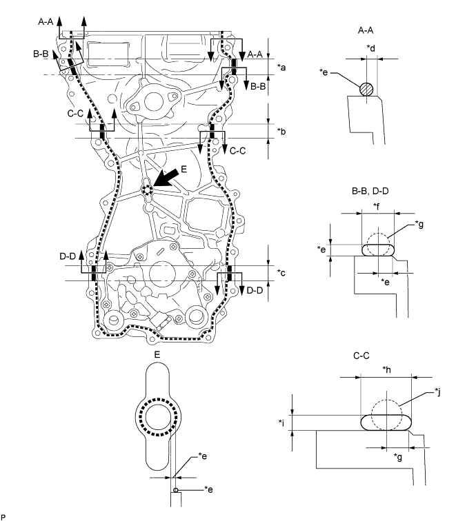
Text in Illustration *a 28 mm (1.102 in.) *b 25 mm (0.984 in.) *c 26 mm (1.024 in.) *d 2.5 mm (0.0984 in.) *e 3.0 mm (0.118 in.) *f 7.0 mm (0.276 in.) or more *g 5.0 mm (0.197 in.) *h 13 mm (0.512 in.) or more *i 3.0 mm (0.118 in.) or more *j 7.0 mm (0.276 in.) -
-
Temporarily install the timing chain cover assembly with the 19 bolts (A, B and C) and 2 nuts.
Standard Bolt Item Length Bolt Diameter Bolt A 30 mm (1.18 in.) 8.0 mm (0.315 in.) Bolt B 35 mm (1.38 in.) 10 mm (0.394 in.) Bolt C 45 mm (1.77 in.) 8.0 mm (0.315 in.) Note
Make sure that there is no oil on the threads of bolt B.
-
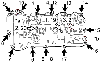
Tighten the 19 bolts and 3 nuts in the order shown in the illustration.
- Torque:
- Bolt A, C and Nut
- 21 N*m { 214 kgf*cm, 15 ft.*lbf }
- Bolt B
- 55 N*m { 561 kgf*cm, 41 ft.*lbf }
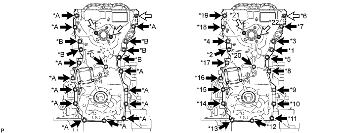
Text in Illustration 
Bolt 
Nut
-
-
INSTALL TIMING GEAR CASE OR TIMING CHAIN CASE OIL SEAL
-
Apply MP grease to the lip of a new timing gear case or timing chain case oil seal.
Note
-
Keep the lip free from foreign matter.
-
Do not allow MP grease to contact the dust seal.
-
-
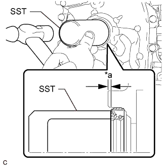
Text in Illustration *a Depth Using SST and a hammer, tap in the timing gear case or timing chain case oil seal until its surface is flush with the timing chain cover assembly edge.
- SST
- 09636-20010
Standard depth 0.75 to 1.45 mm (0.0295 to 0.0571 in.) Note
-
Do not tap in the timing gear case or timing chain case oil seal at an angle.
-
Keep the lip free from foreign matter.
-
Wipe off any MP grease from the crankshaft.
-
-
INSTALL WATER OUTLET SUB-ASSEMBLY
-
Install a new O-ring to the timing chain cover assembly.
-
Install the water outlet sub-assembly with the 2 bolts and nut.
- Torque:
- 10 N*m { 102 kgf*cm, 7 ft.*lbf }
-
-
INSTALL NO. 11 WATER BY-PASS HOSE
-
Install the No. 11 water by-pass hose to the water outlet housing sub-assembly and No. 5 water by-pass pipe, and slide the 2 clamps to secure the 2 hoses.
-
-
INSTALL NO. 13 WATER BY-PASS HOSE
-
Install the No. 13 water by-pass hose to the water outlet housing sub-assembly and No. 3 water by-pass pipe, and slide the 2 clamps to secure the 2 hoses.
-
-
INSTALL CRANKSHAFT PULLEY ASSEMBLY
-
Align the crankshaft pulley set crankshaft key with the key groove of the crankshaft pulley assembly.
-
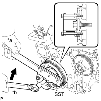
Text in Illustration *a Hold *b Turn Using SST, hold the crankshaft pulley assembly and install the crankshaft pulley set bolt.
- SST
- 09213-54015
- 09330-00021
- Torque:
- 260 N*m { 2651 kgf*cm, 192 ft.*lbf }
Tech Tips
SST (Crankshaft pulley holding tool) fixing bolt part No.: 91551-80650 (2 pcs)
-
-
INSTALL CRANKSHAFT POSITION SENSOR
-
Apply a light coat of engine oil to the O-ring of the crankshaft position sensor.
-
Install the crankshaft position sensor to the timing chain cover assembly with a new bolt.
- Torque:
- 6.5 N*m { 66 kgf*cm, 58 in.*lbf }
Note
-
If a crankshaft position sensor has been struck or dropped, replace it.
-
Make sure that the O-ring is not cracked or moved out of place during installation.
-
Connect the crankshaft position sensor connector.
-
-
INSTALL ENGINE OIL LEVEL DIPSTICK GUIDE
-
Нанесите на новое кольцевое уплотнение тонкий слой моторного масла.
-
Установите на трубку щупа проверки уровня моторного масла кольцевое уплотнение.
-
Закрепите трубку щупа проверки уровня масла болтом.
- Torque:
- 10 Н*м { 102 кгс*см, 7 фунт-сила-футов }
-
-
INSTALL ENGINE OIL LEVEL DIPSTICK
-
Установите щуп проверки уровня моторного масла в трубку щупа проверки уровня моторного масла.
-
-
INSTALL CYLINDER HEAD COVER SUB-ASSEMBLY
-
Apply a light coat of engine oil to 3 new gaskets.
-
Install the 3 gaskets to the camshaft bearing caps.
-
Install a new cylinder head cover gasket to the cylinder head cover sub-assembly.
-
Text in Illustration *1 Timing Chain Cover Assembly *2 Camshaft Housing Sub-assembly *a 5.0 mm (0.197 in.) Seal Packing Apply seal packing as shown in the illustration.
Seal packing Toyota Genuine Seal Packing Black, Three Bond 1207B or equivalent Standard seal diameter 3.0 to 6.0 mm (0.118 to 0.236 in.) Note
-
Be sure to clean and degrease the contact surfaces.
-
Install the cylinder head cover sub-assembly within 3 minutes and tighten the bolts within 15 minutes after applying seal packing.
-
Do not add engine oil within 2 hours of installation.
-
Do not start the engine for at least 2 hours after the installation.
-
-
Text in Illustration *a Pin A *b Pin B Bolt A Bolt B Align the pin holes in the cylinder head cover sub-assembly with pin A and pin B in this order, and then install the cylinder head cover sub-assembly.
-
Temporarily install 3 new seal washers and the 3 bolts labeled B.
-
Temporarily install the 13 bolts labeled A.
-
Tighten the 16 bolts in the order shown in the illustration.
- Torque:
- 12 N*m { 122 kgf*cm, 9 ft.*lbf }
Standard Bolt Item Length Bolt A 25 mm (0.984 in.) Bolt B 35 mm (1.38 in.)
-
-
INSTALL IGNITION COIL ASSEMBLY
-
Install the 4 ignition coil assemblies to the cylinder head cover sub-assembly with the 4 bolts.
- Torque:
- 10 N*m { 102 kgf*cm, 7 ft.*lbf }
Note
If an ignition coil assembly has been struck or dropped, replace it.
Tech Tips
-
Install the same parts to their original positions.
-
Perform "Inspection After Repair" after replacing an ignition coil assembly.
w/ EGR System: Click here
w/o EGR System: Click here
-
Connect the engine wire to the cylinder head cover sub-assembly with the 3 nuts.
- Torque:
- 10 N*m { 102 kgf*cm, 7 ft.*lbf }
-
Connect the 4 ignition coil assembly connectors.
-
-
INSTALL WIRE HARNESS CLAMP BRACKET
-
Install the 2 wire harness clamp brackets to the timing chain cover assembly with the 2 bolts.
- Torque:
- 10 N*m { 102 kgf*cm, 7 ft.*lbf }
-
-
CONNECT ENGINE WIRE
-
Attach the wire harness clamp.
-
Connect the 2 ground wires to the timing chain cover assembly with the 2 bolts.
- Torque:
- 10 N*m { 102 kgf*cm, 7 ft.*lbf }
-
Install the wire harness clamp bracket to the timing chain cover assembly with the bolt.
- Torque:
- 10 N*m { 102 kgf*cm, 7 ft.*lbf }
-
Install the wire harness clamp bracket to the timing chain cover assembly with the 2 bolts.
- Torque:
- 10 N*m { 102 kgf*cm, 7 ft.*lbf }
-
Connect the engine coolant temperature sensor connector.
-
Connect the 4 wire harness clamps.
-
Install the wire harness clamp bracket to the cylinder head cover sub-assembly with the bolt.
- Torque:
- 10 N*m { 102 kgf*cm, 7 ft.*lbf }
-
Attach the 2 wire harness clamps to the wire harness clamp bracket.
-
Connect the engine wire with the 5 nuts.
- Torque:
- 10 N*m { 102 kgf*cm, 7 ft.*lbf }
-
Connect the engine oil pressure switch connector.
-
Connect the 4 ignition coil connectors.
-
Connect the 2 VVT sensor connectors.
-
Connect the 2 camshaft timing oil control valve connectors.
-
Attach the 3 wire harness clamps.
-
-
CONNECT PCV HOSE ASSEMBLY
-
Connect the PCV hose assembly to the PCV valve sub-assembly, and slide the clamp to secure the hose.
-
-
CONNECT OIL COOLER TUBE SUB-ASSEMBLY
-
Connect the oil cooler tube sub-assembly with the 2 bolts.
- Torque:
- 22 N*m { 224 kgf*cm, 16 ft.*lbf }
-
Attach the engine ground wire clamp to the oil cooler tube sub-assembly.
-
-
CONNECT NO. 1 HV WATER PUMP OUTLET PIPE
-
Connect the No. 1 HV water pump outlet pipe to the stiffening crankcase with the 2 bolts.
- Torque:
- 22 N*m { 224 kgf*cm, 16 ft.*lbf }
-
-
INSTALL FAN AND GENERATOR V BELT
Tech Tips
When reusing the fan and generator V belt, check the ribs and back of the fan and generator V belt for wear and cracks. If wear or a crack that reaches the core (at more than 1 point) is found, replace the fan and generator V belt.
-
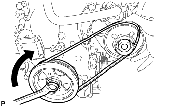
Partially mount the fan and generator V belt on the engine water pump assembly as shown in the illustration. Mount the fan and generator V belt around the engine water pump assembly partially as shown in the illustration.
Note
-
Make sure the fan and generator V belt is securely mounted on the crankshaft pulley assembly.
-
Do not allow slack in the fan and generator V belt.
-
-
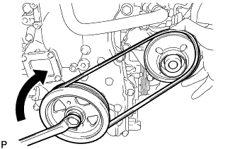
While holding the fan and generator V belt on the engine water pump assembly by hand as shown in the illustration, gradually rotate the crankshaft pulley assembly clockwise to mount the fan and generator V belt on the engine water pump assembly.
CAUTION:
Do not hold any other parts of the fan and generator V belt, or your fingers may get caught between the fan and generator V belt and engine water pump assembly as they are rotated.
Note
-
Guide the fan and generator V belt into the grooves of the engine water pump assembly as the crankshaft pulley assembly is rotated.
-
Make sure the fan and generator V belt is not inside out.
-
-
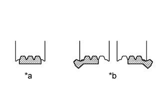
Text in Illustration *a Correct *b Incorrect Rotate the crankshaft pulley assembly until the fan and generator V belt is fully mounted on the engine water pump assembly.
-
Check that the fan and generator V belt is securely mounted on the crankshaft pulley assembly and engine water pump assembly.
Note
Make sure the ribs of the fan and generator V belt are not cracked.
-
Start the engine and check that the fan and generator V belt turns smoothly without any noise.
-
-
INSTALL ENGINE MOTOR CABLE CLAMP BRACKET (for LHD)
-
Установите кронштейн зажима кабеля электропривода двигателя и закрепите его болтом.
- Torque:
- 16 Н*м { 163 кгс*см, 12 фунт-сила-дюймов }
-
Закрепите кабель генератора и кабель электродвигателя на кронштейне зажима кабеля электропривода двигателя.
-
-
INSTALL FUEL PUMP WITH SEAL SUB-ASSEMBLY
-
INSPECT ENGINE OIL LEVEL
-
Put the engine in inspection mode (maintenance mode) Click here.
-
Warm up the engine, stop it and wait 5 minutes. The engine oil level should be between the low level mark and full level mark on the engine oil level dipstick.
If the engine oil level is low, check for leaks and add engine oil to the full level mark.
Note
Do not add engine oil to above the full level mark.
Tech Tips
A certain amount of engine oil will be consumed while driving. In the following situations, oil consumption may increase, and engine oil may need to be refilled in between oil maintenance intervals.
-
When the engine is new, for example directly after purchasing the vehicle or after replacing the engine.
-
If low quality oil or oil of an inappropriate viscosity is used.
-
When driving at high engine speeds or with a heavy load (when towing, etc.), or when accelerating or decelerating frequently while driving.
-
When leaving the vehicle idling for a long time, or when driving frequently in heavy traffic.
When judging the amount of oil consumption, keep in mind that the oil may have become diluted, making it difficult to judge the true level accurately.
-
-
-
INSPECT FOR OIL LEAK
-
Put the engine in inspection mode (maintenance mode) Click here
-
Start the engine. Make sure that there are no oil leaks from the area that was worked on.
-
-
INSTALL NO. 2 ENGINE UNDER COVER
-
Установите защиту картера двигателя № 2 и закрепите ее 4 винтами и 2 уплотнительными шайбами.
-
-
INSTALL FRONT SUSPENSION MEMBER BRACE
-
Установите скобу элемента передней подвески и закрепите ее фиксатором и 4 болтами.
- Torque:
- 52 Н*м { 53 кгс*см, 38 фунт-сила-футов }
-
-
INSTALL ENGINE UNDER COVER
-
Установите защиту картера двигателя и закрепите ее 13 винтами и 3 фиксаторами.
-