БЛОК ДВИГАТЕЛЯ УСТАНОВКА

Tech Tips
Perform "Inspection After Repair" after replacing the engine assembly.
-
w/ EGR System: Click here
-
w/o EGR System: Click here
-
INSTALL WATER OUTLET SUB-ASSEMBLY
-
Install a new O-ring to the timing chain cover assembly.
-
Install the water outlet sub-assembly with the 2 bolts and nut.
- Torque:
- 10 N*m { 102 kgf*cm, 7 ft.*lbf }
-
-
INSTALL ENGINE COOLANT TEMPERATURE SENSOR
-
Install a new gasket onto the engine coolant temperature sensor.
-
Using a 19 mm ball joint lock nut wrench, install the engine coolant temperature sensor to the water outlet sub-assembly.
- Torque:
- 20 N*m { 200 kgf*cm, 14 ft.*lbf }
Note
-
If an engine coolant temperature sensor has been struck or dropped, replace it.
-
Use the formula to calculate special torque values for situations where a ball joint lock nut wrench is combined with a torque wrench Click here.
Tech Tips
Perform "Inspection After Repair" after replacing an engine coolant temperature sensor.
-
w/ EGR System: Click here
-
w/o EGR System: Click here
-
Connect the engine coolant temperature sensor connector.
-
-
INSTALL FUEL INJECTOR SEAL
-
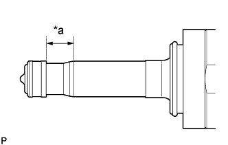
Text in Illustration *a Area to be Cleaned Apply engine conditioner to the area shown in the illustration. Using a piece of cloth, clean carbon deposits from the fuel injector set and its grooves.
Note
-
Do not clean the tip of the fuel injector set.
-
Do not use a wire brush to clean the fuel injector set.
-
If a fuel injector set is dropped or the tip of a fuel injector set is struck, replace it with a new one.
-
-
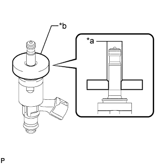
Text in Illustration *a Tapered Inner Portion *b SST (Guide) Apply engine oil to the fuel injector set contact surface of SST (guide). Then attach SST (guide) to the fuel injector set with the chamfer facing the tip of the fuel injector set as shown in the illustration.
- SST
- 09260-39020 ( 09261-03020 )
-
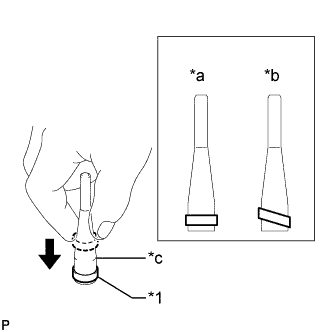
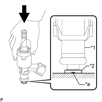
Text in Illustration *1 Fuel Injector Seal *a CORRECT *b INCORRECT *c SST (Holder) Install a new fuel injector seal to SST (holder).
- SST
- 09260-39020 ( 09261-03010 )
Note
Be careful not to install the fuel injector seal to SST (holder) at an angle. Doing so will stretch the fuel injector seal and correcting this problem is very complicated.
-
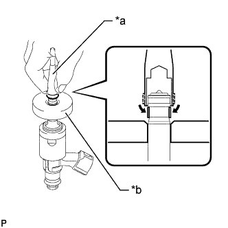
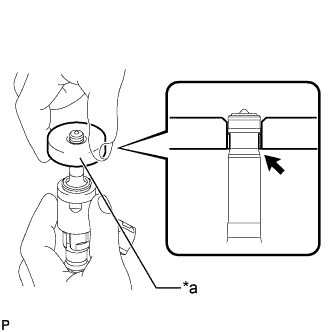
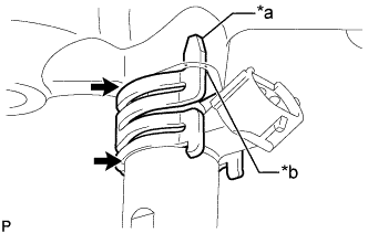
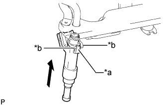
Text in Illustration *a SST (Holder) *b SST (Guide) Install SST (holder) with fuel injector seal to the tip of the fuel injector set. Slide the fuel injector seal downward into the fuel injector set groove (fuel injector set connector side) with your fingers as shown in the illustration.
- SST
- 09260-39020 ( 09261-03010, 09261-03020 )
Tech Tips
Check that the fuel injector seal covers the circumference of the fuel injector set groove as shown in the illustration.
-
Text in Illustration *a SST (Guide) Slowly slide SST (guide) toward the tip of the fuel injector set. When the fuel injector set contact surface of SST (guide) aligns with the fuel injector seal (fuel injector set tip side) as shown in the illustration, hold the position for 5 seconds or more to fully align the fuel injector seal into the fuel injector set groove.
- SST
- 09260-39020 ( 09261-03020 )
Note
Be careful that the fuel injector seal is not pinched between SST (guide) and the fuel injector set groove. Replace the fuel injector seal if it becomes damaged.
Tech Tips
-
Set SST (guide) so that its bottom surface and the fuel injector seal are flush.
-
If there is difficulty in sliding SST upward, slowly wiggle it from side to side while sliding it up the fuel injector set little by little.
-
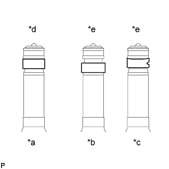
Text in Illustration *a Normal *b Protruding *c Deformed *d CORRECT *e INCORRECT After installing the fuel injector seals, check that they are not scratched, deformed or protruding from the fuel injector set groove.
Note
If a fuel injector seal is scratched, deformed or protruding from the groove, replace it with a new one.
-
-
INSTALL FUEL INJECTOR SET
Tech Tips
Perform "Inspection After Repairs" after replacing the fuel injector assembly.
-
w/ EGR System Click here
-
w/o EGR System Click here
-
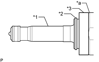
Text in Illustration *1 Fuel Injector Set *2 C-ring *3 Injector Vibration Insulator *a Tapered Side Install a new injector vibration insulator and a new C-ring to the fuel injector set.
Note
-
Install the injector vibration insulator by aligning it with the tapered side of the fuel injector set.
-
Check that the C-ring is securely fit into the groove of the fuel injector set.
-
-
Install a new O-ring and new No. 1 fuel injector back-up ring to the fuel injector set as shown in the illustration.
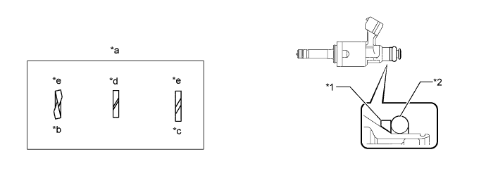
Text in Illustration *1 No. 1 Fuel Injector Back-up Ring *2 O-ring *a No. 1 Fuel Injector Back-up Ring Opening *b Overlapping *c Stretched *d CORRECT *e INCORRECT - - Note
-
Check that there is no foreign matter or damage on the O-ring groove of the fuel injector set.
-
Check that the No. 1 fuel injector back-up ring is installed in the correct direction.
-
Make sure that the No. 1 fuel injector back-up ring and O-ring are installed in the correct order.
-
Check that the alignment openings of the fuel injector back-up rings are not overlapped or stretched as shown in the illustration.
-
After installing the O-ring, check that it is not contaminated with foreign matter and is not damaged.
-
-
Text in Illustration *1 Fuel Injector Set *2 No. 3 Fuel Injector Back-up Ring *a Notch Set a new No. 3 fuel injector back-up ring so that it is level as shown in the illustration, push in the fuel injector set and install the No. 3 fuel injector back-up ring.
Note
-
Make sure that the No. 3 fuel injector back-up ring is oriented correctly.
-
After installing the O-ring, make sure there is no damage or foreign matter.
-
-
Install the nozzle holder clamp to the fuel injector set.
-
Align the protrusion of the nozzle holder clamp with the positioning hole of the fuel delivery pipe and insert the fuel injector set.
Text in Illustration *a Protrusion *b Positioning Hole 
No Gap Note
-
Make sure that there is no foreign matter or damage inside the fuel injector set installation holes (fuel delivery pipe sub-assembly).
-
Do not get gasoline on the O-rings or inside the installation holes.
-
If the fuel injector set is difficult to insert, apply new engine oil to the chamfered part of the fuel injector set installation hole of the fuel delivery pipe sub-assembly. Be careful as it is easier for the fuel injector set to fall out of the fuel delivery pipe sub-assembly in this case.
-
Keep the fuel injector set straight when inserting it into the fuel delivery pipe sub-assembly.
-
Check that there is no gap between the fuel delivery pipe sub-assembly and the nozzle holder clamp.
-
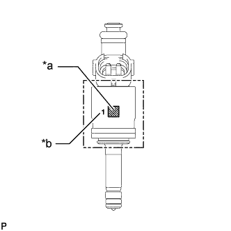
Install 4 fuel injector sets with the same flow classification number (the number to the left of the QR code which is 1, 2 or 3).
Text in Illustration *a QR Code *b Flow Classification Number -
-
-
INSTALL FUEL DELIVERY PIPE SUB-ASSEMBLY
-
Apply lubricant to the fuel injector set installation hole.
-
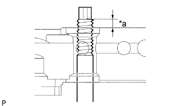
Text in Illustration *a Nut can be attached Insert the stud bolt into the fuel delivery pipe sub-assembly until the screw threads protrude enough so that a nut can be attached.
Note
-
If a fuel injector set is dropped or the tip of a fuel injector set is struck, replace it with a new one.
-
Check that there is no foreign matter or damage on the fuel injector set installation holes of the fuel delivery pipe sub-assembly.
-
When inserting the fuel delivery pipe sub-assembly, push it in evenly without tilting it.
-
-
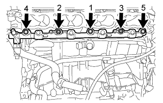
Install the fuel delivery pipe sub-assembly by uniformly tightening the 3 bolts and 2 nuts in several steps in the order shown in the illustration.
- Torque:
- 26 N*m { 265 kgf*cm, 19 ft.*lbf }
-
Connect the 4 fuel injector set connectors.
-
Install the wire harness to the fuel delivery pipe sub-assembly with the 2 bolts.
- Torque:
- 10 N*m { 102 kgf*cm, 7 ft.*lbf }
-
Connect the fuel pressure sensor connector.
Note
Do not pull the wire harness of the fuel pressure sensor excessively.
-
-
INSTALL FUEL INJECTOR ASSEMBLY
Tech Tips
Perform "Inspection After Repairs" after replacing the fuel injector assembly.
-
w/ EGR System Click here
-
w/o EGR System Click here
-
Apply a light coat of spindle oil or gasoline to new O-rings, and install them to each fuel injector assembly.
Note
Check that there is no damage or foreign matter in the grooves of the fuel injector assembly when installing the fuel injector assembly O-rings.
-
Text in Illustration *a Claw *b Plastic Stopper Install the 4 fuel injector assemblies to the fuel delivery pipe.
Note
-
Make sure that the fuel injector assembly is located within the plastic stopper range as shown in the illustration.
-
Check that there is no damage or foreign matter on the fuel injector assembly installation holes.
-
When installing the O-rings, make sure they do not become pinched or cut.
-
-
-
INSTALL FUEL DELIVERY PIPE
-
Install 4 new injector vibration insulators to the cylinder head sub-assembly.
-
Install the 2 No. 1 delivery pipe spacers to the cylinder head sub-assembly.
-
Install the fuel delivery pipe together with the 4 fuel injector assemblies with the 2 bolts.
- Torque:
- 21 N*m { 214 kgf*cm, 15 ft.*lbf }
Note
Be careful not to drop the fuel injector assemblies when installing the fuel delivery pipe.
-
Connect the 4 fuel injector assembly connectors.
-
Connect the No. 6 engine wire connector.
-
Connect the 3 wire harness clamps to the fuel delivery pipe and wire harness clamp bracket.
-
-
SET FUEL PUMP WITH SEAL SUB-ASSEMBLY
-
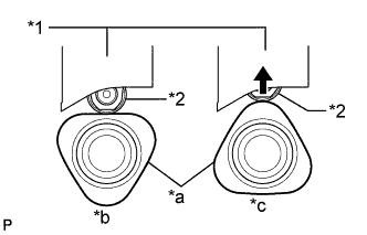
Text in Illustration *1 Fuel Pump lifter guide *2 Fuel Pump lifter assembly *a Cam Lobe *b Correct *c Incorrect Turn the crankshaft pulley so that the flat surface of the cam lobe faces upward from the fuel pump with seal sub-assembly installation hole of the cylinder head cover sub-assembly.
Tech Tips
By performing the above procedure, the cam lobe nose does not push up the drive face of the fuel pump with seal sub-assembly when installing the fuel pump with seal sub-assembly.
-
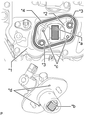
Text in Illustration *1 Cylinder Head Cover Sub-assembly *2 Pump Housing *3 O-ring *4 Fuel Pump Spacer Gasket *a Pump Drive Cam (Engine Oil Application Point) *b Pump Lifter (Engine Oil Application Point) *c Knock Pin *d Positioning Knock Hole Apply 30 cc (1.8 cu in.) of engine oil to the pump drive cam.
-
Apply engine oil to the fuel pump lifter assembly.
-
Apply engine oil to 2 new O-rings and install it to the pump housing.
-
Install a new fuel pump spacer gasket to the cylinder head cover sub-assembly.
-
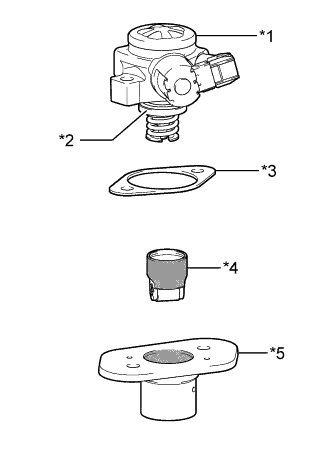
Text in Illustration *1 Fuel Pump with Seal Sub-assembly *2 O-ring *3 Fuel Pump Insulator *4 Fuel Pump Lifter Assembly *5 Fuel Pump Lifter Guide 
Engine Oil Application Point Apply engine oil to a new O-ring and install it to the fuel pump sub-assembly.
-
Remove the fuel pump lifter assembly from the fuel pump lifter guide.
-
Apply engine oil to the inside of the fuel pump lifter guide and the outside of the fuel pump lifter assembly.
-
Install the fuel pump lifter assembly to the fuel pump lifter guide.
-
Install the fuel pump insulator to the fuel pump lifter guide.
-
Set the fuel pump with seal sub-assembly on the cylinder head cover sub-assembly.
-
Temporarily install the fuel pump with seal sub-assembly with the 2 bolts, leaving some allowance for left and right movement.
-
-
TEMPORARILY INSTALL NO. 1 FUEL PIPE SUB-ASSEMBLY
-
Temporarily install the union nuts on the fuel delivery pipe sub-assembly side of the No. 1 fuel pipe sub-assembly until they are completely tightened.
-
Temporarily install the union nuts on the fuel pump with seal sub-assembly side of the No. 1 fuel pipe sub-assembly until they are completely tightened.
Note
Do not damage the seals of the union nuts of the No. 1 fuel pipe sub-assembly when installing.
-
-
INSTALL FUEL PUMP WITH SEAL SUB-ASSEMBLY
Tech Tips
Perform "Inspection After Repair" after replacing the fuel pump with seal sub-assembly.
-
w/ EGR System: Click here
-
w/o EGR System: Click here
-
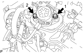
Install the fuel pump with seal sub-assembly by uniformly tightening the 2 bolts in several steps in the order shown in the illustration.
- Torque:
- 15 N*m { 153 kgf*cm, 11 ft.*lbf }
-
Tighten the 2 bolts in the order shown in the illustration again.
- Torque:
- 30 N*m { 306 kgf*cm, 22 ft.*lbf }
-
Connect the fuel pump with seal sub-assembly connector.
-
-
INSTALL NO. 1 FUEL PIPE SUB-ASSEMBLY
-
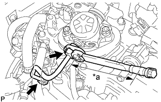
Text in Illustration *a Torque Wrench Fulcrum Length Using a 17 mm union nut wrench, tighten the union nuts on the fuel pump with seal sub-assembly side of the No. 1 fuel pipe sub-assembly.
- Torque:
- Specified tightening torque
- 35 N*m { 357 kgf*cm, 26 ft.*lbf }
Note
-
Do not adjust the torque in the loosening direction.
-
The No. 1 fuel pipe sub-assembly can be reused 10 times.
Tech Tips
-
Calculate the torque wrench reading when changing the fulcrum length of the torque wrench Click here.
-
When using union nut wrench (fulcrum length of 30 mm (1.1811 in.)) + torque wrench (fulcrum length of 180 mm (7.0866 in.)): 30 N*m (306 kgf*cm, 22 ft.*lbf)
-
Using a 17 mm union nut wrench, tighten the union nuts on the fuel delivery pipe sub-assembly side of the No. 1 fuel pipe sub-assembly.
- Torque:
- Specified tightening torque
- 35 N*m { 357 kgf*cm, 26 ft.*lbf }
Note
-
Do not adjust the torque in the loosening direction.
-
The No. 1 fuel pipe sub-assembly can be reused 10 times.
Tech Tips
-
Calculate the torque wrench reading when changing the fulcrum length of the torque wrench Click here.
-
When using union nut wrench (fulcrum length of 30 mm (1.1811 in.)) + torque wrench (fulcrum length of 180 mm (7.0866 in.)): 30 N*m (306 kgf*cm, 22 ft.*lbf)
-
-
INSTALL NO. 1 FUEL PIPE
-
Using a 17 mm deep socket wrench, install a new gasket and the No. 1 fuel pipe.
- Torque:
- 40 N*m { 408 kgf*cm, 30 ft.*lbf }
-
-
INSTALL WATER INLET HOUSING
Note
If a stud bolt is deformed or its threads are damaged, replace it.
-
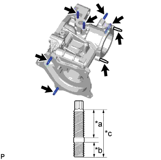
Text in Illustration *a 16 mm (0.63 in.) *b 9 mm (0.354 in.) *c 27 mm (1.06 in.) Using an E6 "TORX" socket wrench, install the 8 stud bolts to the water inlet housing.
- Torque:
- 4.0 N*m { 41 kgf*cm, 35 in.*lbf }
-
Install a new gasket to the water inlet housing.
-
Install the water inlet housing to the cylinder block sub-assembly with the 2 bolts and nut.
- Torque:
- 43 N*m { 438 kgf*cm, 32 ft.*lbf }
Note
Keep the contact surfaces of the cylinder block sub-assembly and water inlet housing free of foreign matter.
Tech Tips
Align the straight pin of the cylinder block sub-assembly with the straight pin hole of the water inlet housing.
-
-
INSTALL NO. 5 WATER BY-PASS PIPE
-
Install a new gasket to the water inlet housing.
-
Install the No. 5 water by-pass pipe to the water inlet housing with the bolt and 2 nuts.
- Torque:
- 10 N*m { 102 kgf*cm, 7 ft.*lbf }
-
Connect the No. 11 water by-pass hose to the water outlet sub-assembly and slide the clip to secure the hose.
-
-
INSTALL WATER INLET WITH THERMOSTAT SUB-ASSEMBLY
-
Install a new gasket on the water inlet with thermostat sub-assembly.
-
Install the water inlet with thermostat sub-assembly with the 2 nuts.
- Torque:
- 10 N*m { 102 kgf*cm, 7 ft.*lbf }
-
-
INSTALL ENGINE WATER PUMP ASSEMBLY
-
Install a new water pump gasket to the engine water pump assembly.
-
Temporarily install the engine water pump assembly with the 3 bolts and 2 nuts.
-
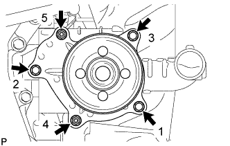
Fully tighten the 3 bolts and 2 nuts in the order shown in the illustration.
- Torque:
- 10 N*m { 102 kgf*cm, 7 ft.*lbf }
-
-
INSTALL WIRE HARNESS CLAMP BRACKET
-
Install the 7 wire harness clamp brackets with the 9 bolts.
- Torque:
- 10 N*m { 102 kgf*cm, 7 ft.*lbf }
-
-
INSTALL ENGINE COVER JOINT
-
Install the 3 engine cover joints.
- Torque:
- 10 N*m { 102 kgf*cm, 7 ft.*lbf }
-
-
INSTALL IGNITION COIL ASSEMBLY
-
Install the 4 ignition coil assemblies to the cylinder head cover sub-assembly with the 4 bolts.
- Torque:
- 10 N*m { 102 kgf*cm, 7 ft.*lbf }
Note
If an ignition coil assembly has been struck or dropped, replace it.
Tech Tips
-
Install the same parts to their original positions.
-
Perform "Inspection After Repair" after replacing an ignition coil assembly.
w/ EGR System: Click here
w/o EGR System: Click here
-
Connect the engine wire to the cylinder head cover sub-assembly with the 3 nuts.
- Torque:
- 10 N*m { 102 kgf*cm, 7 ft.*lbf }
-
Connect the 4 ignition coil assembly connectors.
-
-
INSTALL FRONT NO. 1 ENGINE MOUNTING BRACKET LH
-
Install the front No. 1 engine mounting bracket LH to the cylinder block sub-assembly with the 4 bolts.
- Torque:
- 43 N*m { 438 kgf*cm, 32 ft.*lbf }
-
-
INSTALL FRONT NO. 1 ENGINE MOUNTING BRACKET RH
-
Install the front No. 1 engine mounting bracket RH to the cylinder block sub-assembly with the 4 bolts.
- Torque:
- 43 N*m { 438 kgf*cm, 32 ft.*lbf }
-
-
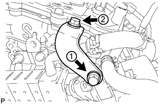
INSTALL NO. 3 WATER BY-PASS PIPE
-
Install the No. 3 water by-pass pipe to the cylinder block sub-assembly with the 3 bolts.
- Torque:
- 21 N*m { 214 kgf*cm, 15 ft.*lbf }
-
Connect the No. 13 water by-pass hose to the water outlet sub-assembly and slide the clip to secure the hose.
-
-
INSTALL NO. 2 WATER BY-PASS PIPE
-
Install the No. 2 water by-pass pipe to the cylinder head sub-assembly with the 2 bolts.
- Torque:
- 10 N*m { 102 kgf*cm, 7 ft.*lbf }
-
-
INSTALL EGR COOLER ASSEMBLY (w/ EGR System)
-
Install the EGR cooler assembly to the cylinder head sub-assembly with the 2 nuts and bolt.
- Torque:
- 21 N*m { 214 kgf*cm, 15 ft.*lbf }
-
Connect the No. 4 water by-pass hose to the EGR valve assembly and slide the clip to secure the hose.
-
Connect the No. 12 water by-pass hose to the EGR valve assembly and slide the clip to secure the hose.
-
Connect the No. 5 water by-pass hose to the EGR cooler assembly and slide the clip to secure the hose.
-
Connect the No. 6 water by-pass hose to the EGR cooler assembly and slide the clip to secure the hose.
-
-
INSTALL EGR VALVE BRACKET (w/ EGR System)
-
Temporarily install the EGR valve bracket to the EGR valve assembly and cylinder head sub-assembly with the 2 bolts.
Tech Tips
Tighten the bolts until they are seated on the EGR valve bracket.
-
Tighten the 2 bolts in the order shown in the illustration.
- Torque:
- 27 N*m { 275 kgf*cm, 20 ft.*lbf }
-
-
INSTALL WATER BY-PASS PIPE (w/o EGR System)
-
Install the water by-pass pipe to the cylinder head sub-assembly with the bolt and nut.
- Torque:
- 21 N*m { 214 kgf*cm, 15 ft.*lbf }
-
Connect the No. 5 water by-pass hose and No. 6 water by-pass hose to the water by-pass pipe and slide the 2 clips to secure the hoses.
-
-
INSTALL NO. 1 WATER BY-PASS PIPE
-
Install a new gasket and the No. 1 water by-pass pipe with the bolt and 2 nuts.
- Torque:
- 10 N*m { 102 kgf*cm, 7 ft.*lbf }
-
Connect the water by-pass hose to the No. 2 water by-pass pipe and slide the clip to secure the hose.
-
-
INSTALL NO. 1 COMPRESSOR MOUNTING BRACKET
-
Install the No. 1 compressor mounting bracket with the 5 bolts.
- Torque:
- 25 N*m { 250 kgf*cm, 18 ft.*lbf }
-