СИСТЕМА SFI (для моделей с системой РОГ), Diagnostic DTC:P1235
| DTC Code | DTC Name |
|---|---|
| P1235 | High Pressure Fuel Pump Circuit |
DESCRIPTION
The high-pressure direct injection fuel system consists of a spill control valve, check valve, relief valve and pump plunger. The spill control valve adjusts the return volume of the high-pressure fuel. The check valve mechanically opens and closes the paths to the fuel delivery pipes. The relief valve releases the fuel back to the fuel tank if the high-pressure fuel system malfunctions. The fuel pump (for high pressure) is installed to the cylinder head cover and operated by a cam installed to the rear end of the intake camshaft. Rotation of the camshaft moves the pump plunger inside the fuel pump (for high pressure) up and down, pressurizing the fuel. The pressurized fuel opens the check valve and is pumped into the fuel delivery pipe.
| DTC No. | DTC Detection Condition | Trouble Area |
|---|---|---|
| P1235 | Open or short in fuel pump (for high pressure) circuit for 0.5 second or more (1 trip detection logic) |
|
MONITOR STRATEGY
| Required Sensors/Components | Fuel pump (for high pressure) |
| Frequency of Operation | Continuous |
CONFIRMATION DRIVING PATTERN
-
Connect the GTS to the DLC3.
-
Turn the power switch on (IG) and turn the GTS on.
-
Clear the DTCs (even if no DTCs are stored, perform the clear DTC procedure).
-
Turn the power switch off and wait for 30 seconds.
-
Turn the power switch on (IG) and turn the GTS on.
-
Put the engine in inspection mode (maintenance mode) Click here.
-
Start the engine.
-
Idle the engine for 10 seconds.
-
Enter the following menus: Powertrain / Engine and ECT / Trouble Codes.
-
Read the pending DTCs.
Tech Tips
-
If a pending DTC is output, the system is malfunctioning.
-
If a pending DTC is not output, perform the following procedure.
-
-
Enter the following menus: Powertrain / Engine and ECT / Utility / All Readiness.
-
Input the DTC: P1235.
-
Check the DTC judgment result.
GTS Display Description NORMAL
-
DTC judgment completed
-
System normal
ABNORMAL
-
DTC judgment completed
-
System abnormal
INCOMPLETE
-
DTC judgment not completed
-
Perform driving pattern after confirming DTC enabling conditions
N/A
-
Unable to perform DTC judgment
-
Number of DTCs which do not fulfill DTC preconditions has reached ECU memory limit
Tech Tips
-
If the judgment result shows NORMAL, the system is normal.
-
If the judgment result shows ABNORMAL, the system has a malfunction.
-
If the judgment result shows INCOMPLETE or N/A, perform the Confirmation Driving Pattern and check the DTC judgment result again.
-
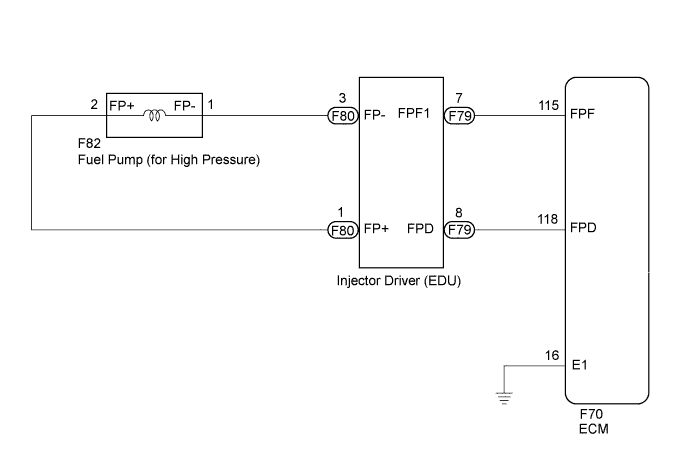
WIRING DIAGRAM
INSPECTION PROCEDURE
Tech Tips
-
If the current from the INJ relay is cut because DTC P062D is stored, DTC P1235 will be stored even if the fuel pump (for high pressure) is normal.
-
Read freeze frame data using the GTS. The ECM records vehicle and driving condition information as freeze frame data the moment a DTC is stored. When troubleshooting, freeze frame data can help determine if the vehicle was moving or stationary, if the engine was warmed up or not, if the air fuel ratio was lean or rich, and other data from the time the malfunction occurred.
PROCEDURE
-
INSPECT FUEL PUMP (FOR HIGH PRESSURE)
-
Inspect the fuel pump (for high pressure) Click here.
Tech Tips
Perform "Inspection After Repair" after replacing the fuel pump (for high pressure) Click here.
NG 
REPLACE FUEL PUMP (FOR HIGH PRESSURE) Click here
OK 
-
-
CHECK HARNESS AND CONNECTOR (INJECTOR DRIVER (EDU) - FUEL PUMP (FOR HIGH PRESSURE))
-
Disconnect the injector driver (EDU) connector.
-
Disconnect the fuel pump (for high pressure) connector.
-
Measure the resistance according to the value(s) in the table below.
Standard Resistance Tester Connection Condition Specified Condition F80-1 (FP+) - F82-2 (FP+) Always Below 1 Ω F80-3 (FP-) - F82-1 (FP-) Always Below 1 Ω F80-1 (FP+) or F82-2 (FP+) - Body ground Always 10 kΩ or higher F80-3 (FP-) or F82-1 (FP-) - Body ground Always 10 kΩ or higher
NG
REPAIR OR REPLACE HARNESS OR CONNECTOR
OK
-
-
CHECK HARNESS AND CONNECTOR (ECM - INJECTOR DRIVER (EDU))
-
Disconnect the ECM connector.
-
Disconnect the injector driver (EDU) connector.
-
Measure the resistance according to the value(s) in the table below.
Standard Resistance Tester Connection Condition Specified Condition F70-115 (FPF) - F79-7 (FPF1) Always Below 1 Ω F70-118 (FPD) - F79-8 (FPD) Always Below 1 Ω F70-115 (FPF) or F79-7 (FPF1) - Body ground Always 10 kΩ or higher F70-118 (FPD) or F79-8 (FPD) - Body ground Always 10 kΩ or higher
NG
REPAIR OR REPLACE HARNESS OR CONNECTOR
OK
-
-
REPLACE INJECTOR DRIVER (EDU)
-
Replace the injector driver (EDU) Click here.
NEXT
-
-
CHECK WHETHER DTC OUTPUT RECURS (DTC P1235)
-
Connect the GTS to the DLC3.
-
Turn the power switch on (IG).
-
Turn the GTS on.
-
Clear DTCs.
-
Turn the power switch off and wait for at least 30 seconds.
-
Turn the power switch on (IG).
-
Turn the GTS on.
-
Drive the vehicle in accordance with the driving pattern described in Confirmation Driving Pattern.
-
Enter the following menus: Powertrain / Engine and ECT / Trouble Codes.
-
Read the DTCs.
Result Result Proceed to DTC is not output A DTC P1235 is output B
B
REPLACE ECM Click here
A 
END
-