ПРЕОБРАЗОВАТЕЛЬ-ИНВЕРТОР СНЯТИЕ
-
PRECAUTION
CAUTION:
Be sure to read Precaution thoroughly before servicing Click here.
Note
After turning the power switch off, waiting time may be required before disconnecting the cable from the battery terminal. Therefore, make sure to read the disconnecting the cable from the battery terminal notice before proceeding with work Click here.
-
REMOVE LUGGAGE COMPARTMENT FLOOR MAT
-
Снимите напольный коврик багажного отделения.
-
-
REMOVE LUGGAGE COMPARTMENT TRIM COVER LH
-
Снимите левую облицовочную накладку багажного отделения.
-
-
DISCONNECT CABLE FROM AUXILIARY NEGATIVE BATTERY TERMINAL
Note
When disconnecting the cable, some systems need to be initialized after the cable is reconnected Click here.
-
Disconnect the cable from the auxiliary battery negative (-) terminal.
Tech Tips
Both cables should be disconnected to prevent the AMD terminal from shorting to ground.
-
Remove the terminal cover.
-
Remove the nut and disconnect the cable from the auxiliary battery positive (+) terminal.
Tech Tips
Both cables should be disconnected to prevent the AMD terminal from shorting to ground.
-
-
REMOVE SERVICE PLUG GRIP
-
REMOVE ENGINE ROOM SIDE COVER
-
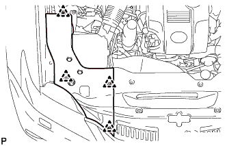
Освободите 4 фиксатора и снимите боковую крышку моторного отсека.
-
-
REMOVE COOL AIR INTAKE DUCT SEAL
-
Снимите 7 фиксаторов и сальник впускного воздухопровода холодного воздуха.
-
-
REMOVE NO. 1 AIR CLEANER INLET
-
Выверните болт и снимите входной патрубок воздушного фильтра № 1.
-
-
REMOVE ENGINE UNDER COVER
-
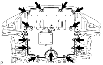
Выверните 13 винтов, расцепите 3 фиксатора и снимите защиту картера двигателя.
-
-
DRAIN COOLANT (for Inverter)
Note
-
Do not reuse the drained coolant because it may contain foreign objects.
-
Collect the drained coolant and measure its volume to establish a benchmark. When adding coolant, make sure to add more coolant than the measured amount.
-
Remove the reservoir tank cap.
-
Loosen the drain cock plug.
CAUTION:
To avoid the danger of being burned, do not remove the reservoir tank cap while the coolant for the inverter is still hot.
-
-
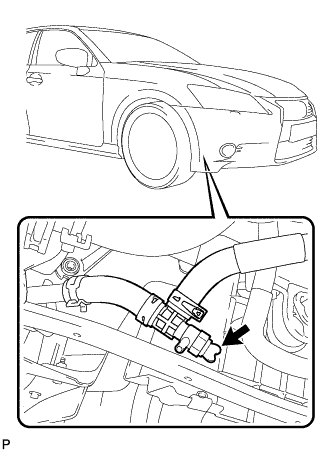
DISCONNECT INVERTER COOLING HOSE ASSEMBLY (for RHD)
Note
-
Make sure to disconnect the inverter cooling hose from the inverter cooling pipe assembly and drain all the coolant, since some coolant will remain after removing the drain plug.
-
Collect the drained coolant and measure its volume to establish a benchmark. When adding coolant, make sure to add more coolant than the measured amount.
-
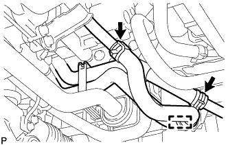
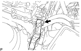
Detach the inverter cooling hose clamp from the inverter cooling pipe assembly.
Tech Tips
Detach the clamp from the inverter cooling pipe assembly, since the clamp is attached to the inverter cooling hose.
-
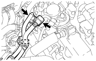
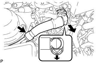
Slide the 2 hose clamps of the inverter cooling hoses shown in the illustration, and then disconnect the inverter cooling hoses from the inverter cooling pipes.
Note
Apply insulating tape to the pipes and in the disconnected hoses or cover the pipes and hoses with plastic bags to prevent entry of foreign matter.
-
-
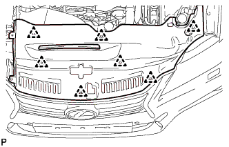
REMOVE NO. 1 ENGINE COVER SUB-ASSEMBLY
-
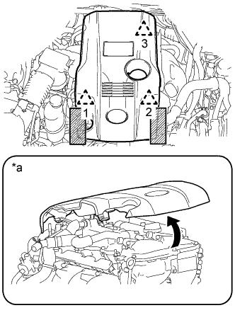
Обозначения на рисунке *a При отсоединении фиксатора с задней стороны крышки 
Зоны, подлежащие захвату при подъеме крышки двигателя № 1 в сборе Поместите обе руки с любой стороны крышки двигателя № 1 в сборе, как показано на рисунке, чтобы отсоединить левый и правый фиксаторы (1 и 2) рядом с передней частью крышки. Затем поднимите крышку, чтобы отсоединить фиксатор (3) с задней стороны, и снимите крышку.
Note
-
Если левая и правая стороны, а также передняя и задняя стороны крышки будут подниматься одновременно, крышка может быть повреждена.
-
Если не будет в точности соблюдаться порядок выполнения действий, фиксатор с задней стороны крышки может быть поврежден.
-
При попытке снять крышку, открепив только один из передних фиксаторов, крышка может быть повреждена.
-
-
-
REMOVE AIR CLEANER CAP WITH NO. 2 AIR CLEANER HOSE (for LHD)
-
Disconnect the mass air flow meter sub-assembly connector.
-
Disconnect the wire harness clamp from the air cleaner cap with No. 2 air cleaner hose.
-
Detach the 4 clamps.
-
Loosen the hose clamp to remove the air cleaner cap with No. 2 air cleaner hose.
-
-
REMOVE AIR CLEANER HOSE ASSEMBLY (for LHD)
-
Slide the clamp and disconnect the ventilation hose from the cylinder head cover sub-assembly.
-
Loosen the hose clamp to remove the air cleaner hose assembly from the throttle body with motor assembly.
-
-
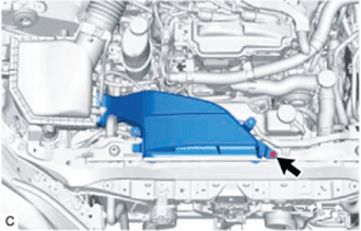
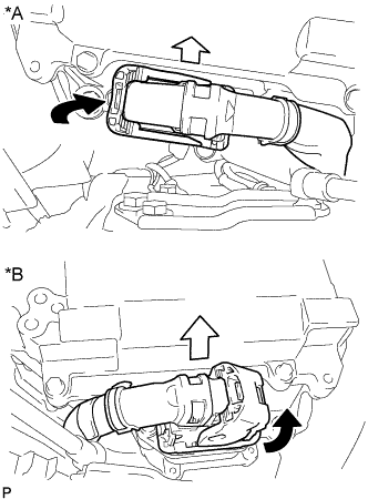
REMOVE INVERTER COVER
-
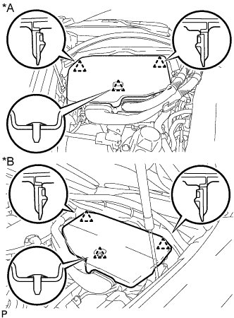
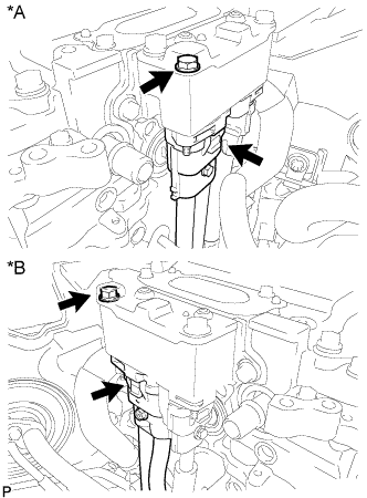
Text in Illustration *A for LHD *B for RHD Raise the front of the inverter cover to detach the clip. Then remove the 2 inverter cover clips from the bracket, and remove the inverter cover.
-
-
REMOVE CONNECTOR COVER ASSEMBLY
CAUTION:
-
Do not touch the high voltage connectors and terminals for 10 minutes after the service plug grip is removed.
-
Wear insulated gloves.
Note
Do not start the hybrid system with the service plug grip removed because it may cause a malfunction.
-
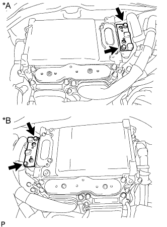
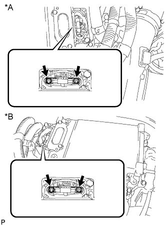
Text in Illustration *A for LHD *B for RHD Using an insulated tool, remove the 2 bolts and connector cover assembly.
Note
-
Make sure to pull the connector cover assembly straight up, as a connector is connected to the bottom of the connector cover assembly.
-
Do not allow any foreign objects or water to enter the inverter with converter assembly.
-
-
-
CHECK TERMINAL VOLTAGE
CAUTION:
Wear insulated gloves.
Note
Do not allow any foreign objects or water to enter the inverter with converter assembly.
-
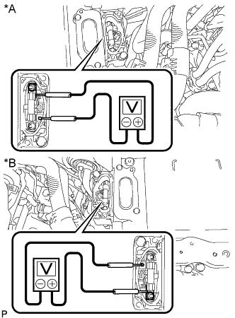
Text in Illustration *A for LHD *B for RHD Using a voltmeter, measure the voltage between the terminals of the 2 phase connectors.
Standard voltage 0 V Tech Tips
Use a measuring range of DC 750 V or more on the voltmeter.
-
-
TEMPORARILY INSTALL CONNECTOR COVER ASSEMBLY
CAUTION:
Wear insulated gloves.
-
Temporarily install the connector cover assembly with the bolt to prevent any foreign objects or water from entering the inverter with converter assembly.
-
-
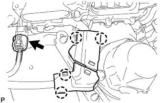
REMOVE INVERTER MOTOR CABLE BRACKET ASSEMBLY
-
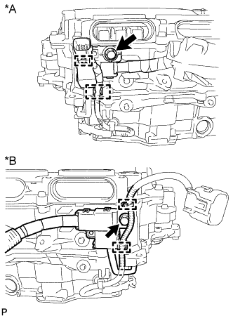
Text in Illustration *A for LHD *B for RHD Detach the 2 clamps from the inverter motor cable bracket assembly.
-
Remove the 2 bolts and inverter motor cable bracket assembly.
-
-
REMOVE INVERTER TERMINAL COVER
CAUTION:
Wear insulated gloves.
-
for Type A:
-
Text in Illustration *A for LHD *B for RHD Using an insulated tool, remove the 2 bolts and inverter terminal cover.
Note
-
Make sure to pull the inverter terminal cover straight up, as a connector is connected to the bottom of the inverter terminal cover.
-
Do not touch the inverter terminal cover waterproofing rubber.
-
-
-
for Type B:
-
Text in Illustration *A for LHD *B for RHD Using an insulated tool, remove the 3 bolts and inverter terminal cover.
Note
-
Make sure to pull the inverter terminal cover straight up, as a connector is connected to the bottom of the inverter terminal cover.
-
Do not touch the inverter terminal cover waterproofing rubber.
-
-
-
-
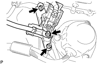
DISCONNECT GENERATOR CABLE
CAUTION:
Wear insulated gloves.
-
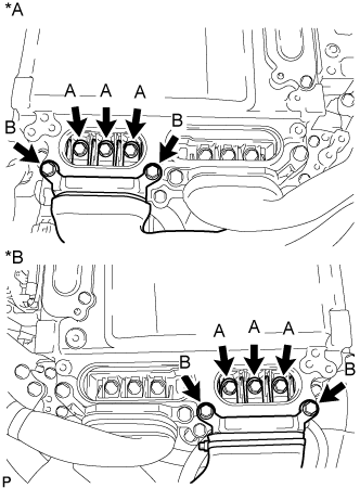
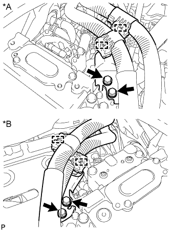
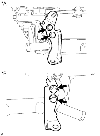
Text in Illustration *A for LHD *B for RHD Using an insulated tool, remove the 3 bolts labeled A in the illustration.
Note
-
Do not damage the terminals, connector housings or inverter with converter assembly when disconnecting them.
-
Do not touch the connector waterproofing rubber or terminals.
-
Do not allow any foreign objects or water to enter the inverter with converter assembly.
-
-
Using an insulated tool, remove the 2 bolts labeled B in the illustration.
Note
-
Do not damage the terminals, connector housings or inverter with converter assembly when disconnecting them.
-
Do not touch the connector waterproofing rubber or terminals.
-
Insulate the removed terminals with insulating tape.
-
Do not allow any foreign objects or water to enter the inverter with converter assembly.
-
-
-
DISCONNECT MOTOR CABLE
CAUTION:
Wear insulated gloves.
-
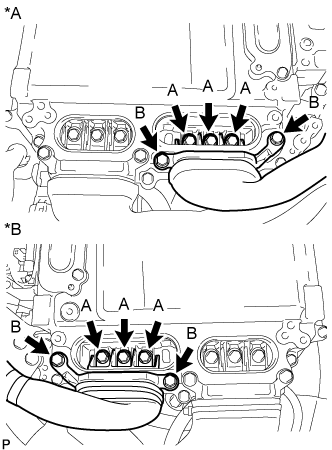
Text in Illustration *A for LHD *B for RHD Using an insulated tool, remove the 3 bolts labeled A in the illustration.
Note
-
Do not damage the terminals, connector housings or inverter with converter assembly when disconnecting them.
-
Do not touch the connector waterproofing rubber or terminals.
-
Do not allow any foreign objects or water to enter the inverter with converter assembly.
-
-
Using an insulated tool, remove the 2 bolts labeled B in the illustration.
Note
-
Do not damage the terminals, connector housings or inverter with converter assembly when disconnecting them.
-
Do not touch the connector waterproofing rubber or terminals.
-
Insulate the removed terminals with insulating tape.
-
Do not allow any foreign objects or water to enter the inverter with converter assembly.
-
-
-
DISCONNECT FUEL TUBE SUB-ASSEMBLY (for LHD)
-
Отсоедините зажим топливопровода № 1 от кронштейна зажима жгута проводов.
-
Отсоедините топливопровод в сборе от топливного насоса с уплотнением в сборе (см. стр. Click here).
-
Отсоедините топливопровод от топливной рампы (см. стр. Click here).
-
-
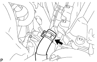
REMOVE NO. 1 INVERTER COOLING OUTLET HOSE (for LHD)
-
Release the retainer and disconnect the No. 1 inverter cooling outlet hose from the inverter with converter assembly.
-
Slide the clamp and remove the No. 1 inverter cooling outlet hose.
Note
Apply insulating tape to the pipes and in the disconnected hoses, or cover the pipes and hoses with plastic bags to prevent foreign matter from entering the cooling system and to prevent coolant from spilling near the inverter with converter assembly.
-
-
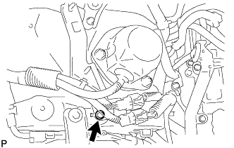
DISCONNECT NO. 1 INVERTER COOLING INLET HOSE (for LHD)
-
Slide the clamp and disconnect the No. 1 inverter cooling inlet hose from the inverter with converter assembly.
Note
Apply insulating tape to the pipes and in the disconnected hoses, or cover the pipes and hoses with plastic bags to prevent foreign matter from entering the cooling system and to prevent coolant from spilling near the inverter with converter assembly.
-
-
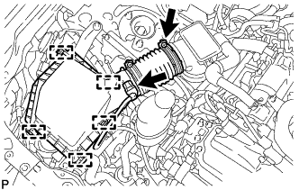
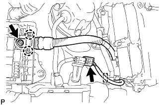
REMOVE INVERTER INLET PIPE ASSEMBLY (for RHD)
-
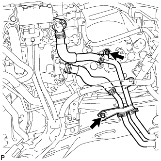
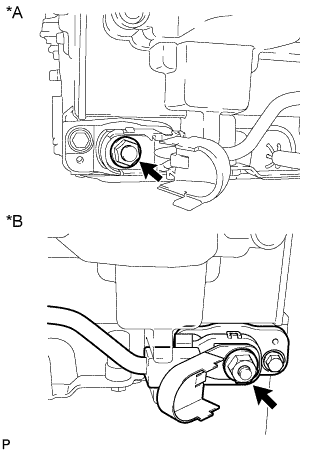
Remove the bolt and nut, and disconnect the inverter inlet pipe assembly from the suspension tower LH.
Note
Be sure to disconnect the inverter inlet pipe assembly before disconnecting the inverter cooling hose so that no excessive force is applied to the pipe and bracket of the inverter inlet pipe assembly.
-
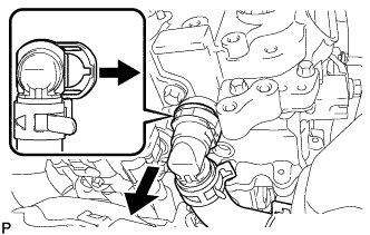
Release the retainer and disconnect the No. 2 inverter cooling outlet hose from the inverter with converter assembly.
Note
Apply insulating tape to the pipes and in the disconnected hoses, or cover the pipes and hoses with plastic bags to prevent foreign matter from entering the cooling system and to prevent coolant from spilling near the inverter with converter assembly.
-
-
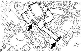
DISCONNECT NO. 2 INVERTER COOLING INLET HOSE (for RHD)
-
Slide the clamp and disconnect the No. 2 inverter cooling inlet hose from the inverter with converter assembly.
Note
Apply insulating tape to the pipes and in the disconnected hoses, or cover the pipes and hoses with plastic bags to prevent foreign matter from entering the cooling system and to prevent coolant from spilling near the inverter with converter assembly.
-
-
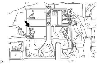
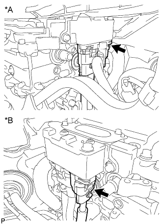
DISCONNECT INVERTER BUS-BAR PLATE SUB-ASSEMBLY
-
for LHD:
-
Detach the 4 claws and disconnect the connector cover.
-
Disconnect the connector.
-
Remove the 3 nuts and disconnect the wire harness and inverter bus-bar plate sub-assembly.
-
Remove the bolt and disconnect the wire harness bracket.
-
-
for RHD:
-
Remove the relay block cover.
-
Disconnect the connector and detach the clamp.
-
Remove the nut, detach the 2 claws and disconnect the inverter bus-bar plate sub-assembly.
-
-
-
REMOVE INVERTER WITH CONVERTER ASSEMBLY
CAUTION:
Wear insulated gloves.
-
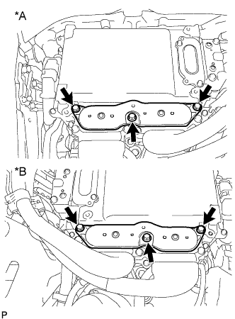
Loosen the 6 bolts as shown in the illustration.
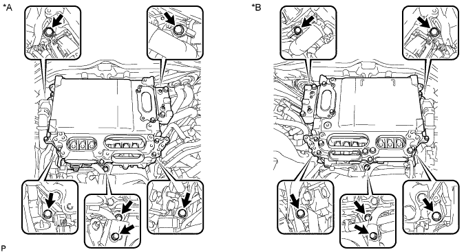
Text in Illustration *A for LHD *B for RHD Note
-
Since the inverter with converter is very heavy, 2 people are needed to remove the inverter with converter assembly. When removing the inverter with converter assembly, do not damage the parts around it.
-
To prevent damage, do not hold the inverter with converter assembly by the connectors.
-
To prevent damage due to static electricity, do not touch the terminals of the disconnected connectors.
-
-
Text in Illustration *A for LHD *B for RHD Raise the lock lever and disconnect the connector.
-
Remove the bolt and connector cover assembly.
Note
-
Make sure to pull the connector cover assembly straight up, as a connector is connected to the bottom of the cover.
-
Do not allow any foreign objects or water to enter the inverter with converter assembly.
-
-
Text in Illustration *A for LHD *B for RHD Disconnect the air conditioning harness.
Note
-
Do not damage the terminals, connector housings or inverter with converter assembly when disconnecting them.
-
Do not touch the connector waterproofing rubber or terminals.
-
Insulate the removed terminals with insulating tape.
-
Do not allow any foreign objects or water to enter the inverter with converter assembly.
-
-
Text in Illustration *A for LHD *B for RHD Using an insulated tool, remove the bolt and disconnect the No. 4 floor wire.
Note
-
Do not damage the terminals, connector housings or inverter with converter assembly when disconnecting them.
-
Do not touch the connector waterproofing rubber or terminals.
-
Insulate the removed terminals with insulating tape.
-
Do not allow any foreign objects or water to enter the inverter with converter assembly.
-
-
Temporarily install the connector cover assembly with the bolt to prevent any foreign objects or water from entering the inverter with converter assembly.
-
Remove the 6 bolts, inverter with converter assembly and No. 6 inverter bracket.
Note
-
Since the inverter with converter assembly is very heavy, 2 people are needed to remove the inverter with converter assembly. When removing the inverter with converter assembly, do not damage the parts around it.
-
Insulate the removed terminals with insulating tape.
-
To prevent damage, do not hold the inverter with converter by the connectors.
-
To prevent damage due to static electricity, do not touch the terminals of the disconnected connectors.
-
-
Even after the coolant is drained, coolant remains in the inverter with converter assembly due to its internal structure. Therefore, seal or cover the pipes when removing the inverter with converter assembly to prevent coolant from spilling out or foreign matter from entering the inverter with converter assembly.
-
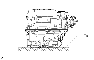
Text in Illustration *a Cushion When removing and storing the inverter with converter assembly, make sure to install the inverter terminal cover and place a cushion under the inverter with converter assembly to protect it.
Note
Do not place the inverter with converter assembly upside down.
-
-
REMOVE NO. 4 INVERTER BRACKET
-
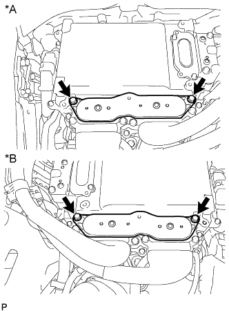
Text in Illustration *A for LHD *B for RHD Remove the 2 bolts and No. 4 inverter bracket.
-
for RHD:
Remove the bolt and wire harness bracket.
-
-
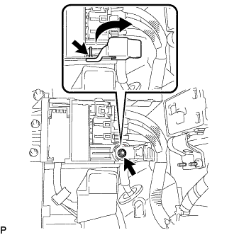
REMOVE INVERTER BUS-BAR PLATE SUB-ASSEMBLY
-
Text in Illustration *A for LHD *B for RHD Detach the 2 wire harness clamps and remove the bolt.
-
Text in Illustration *A for LHD *B for RHD Open the cover.
Note
Do not twist the cover excessively when opening it.
-
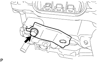
Remove the nut and inverter bus-bar plate sub-assembly.
Note
-
If the stud bolt becomes loose when removing the nut, tighten the stud bolt to a torque of 10 N*m (107 kgf*cm 7 ft.*lbf).
-
If the inverter bus-bar plate is dropped or deformed, replace it with a new one.
-
-
-
REMOVE HIGH VOLTAGE FUSE
CAUTION:
Wear insulated gloves.
Tech Tips
Perform this procedure only when replacement of the high voltage fuse is necessary.
-
Remove the bolt and connector cover assembly.
Note
-
Make sure to pull the connector cover assembly straight up, as a connector is connected to the bottom of the cover.
-
Do not allow any foreign objects or water to enter the inverter with converter assembly.
-
-
Text in Illustration *A for LHD *B for RHD Remove the 2 nuts and high voltage fuse.
-
Temporarily install the connector cover assembly with the bolt to prevent any foreign objects or water from entering the inverter with converter assembly.
-