СИСТЕМА УПРАВЛЕНИЯ ГИБРИДНОЙ СИСТЕМОЙ, Diagnostic DTC:P0AE7-224
| DTC Code | DTC Name |
|---|---|
| P0AE7-224 | Hybrid Battery Precharge Contactor Control Circuit High |
DESCRIPTION
Refer to the description for DTC P0AE6-225 Click here.
| DTC No. | DTC Detection Condition | Trouble Area |
|---|---|---|
| P0AE7-224 | Open or +B short in SMRP circuit Primary circuit of SMRP is malfunctioning. (2 trip detection logic) |
|
| DTC No. | Data List |
|---|---|
| P0AE7-224 |
|
WIRING DIAGRAM
Refer to the wiring diagram for DTC P0AE6-225 Click here.
INSPECTION PROCEDURE
CAUTION:
-
Before inspecting the high-voltage system or disconnecting the low voltage connector of the inverter with converter assembly, take safety precautions such as wearing insulated gloves and removing the service plug grip to prevent electrical shocks. After removing the service plug grip, put it in your pocket to prevent other technicians from accidentally reconnecting it while you are working on the high-voltage system.
-
After removing the service plug grip, wait for at least 10 minutes before touching any of the high-voltage connectors or terminals. After waiting for 10 minutes, check the voltage at the terminals in the inspection point in the inverter with converter assembly. The voltage should be 0 V before beginning work Click here.
Tech Tips
Waiting for at least 10 minutes is required to discharge the high-voltage capacitor inside the inverter with converter assembly.
Note
After turning the power switch off, waiting time may be required before disconnecting the cable from the negative (-) auxiliary battery terminal. Therefore, make sure to read the disconnecting the cable from the negative (-) auxiliary battery terminal notices before proceeding with work Click here.
Tech Tips
-
If DTC P0AE7-224 is output, the power switch cannot be turned on (READY).
-
After the repair, clear the DTCs, perform the following procedure and check that the same DTC (including pending DTC) is not output.
-
Turn the power switch off and wait for 30 seconds or more.
-
Turn the power switch on (READY) and wait for 30 seconds or more.
-
Turn the power switch off and wait for 60 seconds or more.
PROCEDURE
-
READ VALUE USING GTS (SMRP STATUS)
-
Connect the GTS to the DLC3.
-
Turn the power switch on (IG).
-
Enter the following menus: Powertrain / Hybrid Control / Data List / SMRP Status.
-
Read the Data List.
Standard Tester Display Switch Condition Specified Condition SMRP Status Power switch on (IG) OFF -
Turn the power switch off.
NG 
CHECK HARNESS AND CONNECTOR (SMRP VOLTAGE) Click here
OK 
-
-
CHECK CONNECTOR CONNECTION CONDITION (POWER MANAGEMENT CONTROL ECU CONNECTOR)
-
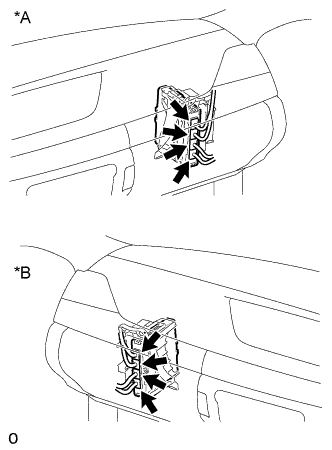
Text in Illustration *A for LHD *B for RHD Check the connector connections and contact pressure of the relevant terminals for the power management control ECU connectors Click here.
OK The connectors are connected securely and there are no contact pressure problems.
NG 
CONNECT SECURELY
OK
-
-
CHECK CONNECTOR CONNECTION CONDITION (NO. 2 HYBRID BATTERY PACK WIRE CONNECTOR)
CAUTION:
Be sure to wear insulated gloves.
-
Check that the service plug grip is not installed.
Note
After removing the service plug grip, do not turn the power switch on (READY), unless instructed by the repair manual because this may cause a malfunction.
-
Remove the front luggage compartment trim cover Click here.
-
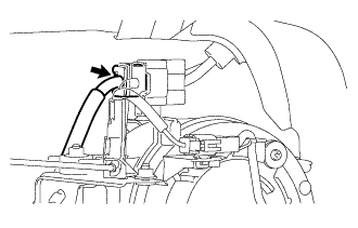
Check the connector connections and contact pressure of the relevant terminals for the No. 2 hybrid battery pack wire connector Click here.
OK The connector is connected securely and there are no contact pressure problems. -
Install the front luggage compartment trim cover.
NG
CONNECT SECURELY
OK
-
-
CHECK CONNECTOR CONNECTION CONDITION (HYBRID BATTERY JUNCTION BLOCK ASSEMBLY CONNECTOR)
CAUTION:
Be sure to wear insulated gloves.
-
Check that the service plug grip is not installed.
Note
After removing the service plug grip, do not turn the power switch on (READY), unless instructed by the repair manual because this may cause a malfunction.
-
Remove the upper hybrid battery cover sub-assembly Click here.
-
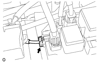
Check the connector connections and contact pressure of the relevant terminals for the hybrid battery junction block assembly connector Click here.
OK The connectors are connected securely and there are no contact pressure problems. -
Install the upper hybrid battery cover sub-assembly.
NG
CONNECT SECURELY
OK 
CHECK FOR INTERMITTENT PROBLEMS Click here
-
-
CHECK HARNESS AND CONNECTOR (SMRP VOLTAGE)
-
Turn the power switch on (IG).
-
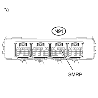
Text in Illustration *a Component with harness connected
(Power Management Control ECU)
Measure the voltage according to the value(s) in the table below.
Standard Voltage Tester Connection Switch Condition Specified Condition N91-3 (SMRP) - Body ground Power switch on (IG) Below 1 V -
Turn the power switch off.
NG
CHECK HARNESS AND CONNECTOR (POWER MANAGEMENT CONTROL ECU - BODY GROUND) Click here
OK
-
-
CHECK CONNECTOR CONNECTION CONDITION (POWER MANAGEMENT CONTROL ECU CONNECTOR)
-
Text in Illustration *A for LHD *B for RHD Check the connector connections and contact pressure of the relevant terminals for the power management control ECU connectors Click here.
OK The connectors are connected securely and there are no contact pressure problems.
NG
CONNECT SECURELY
OK
REPLACE POWER MANAGEMENT CONTROL ECU Click here
-
-
CHECK HARNESS AND CONNECTOR (POWER MANAGEMENT CONTROL ECU - BODY GROUND)
-
Disconnect the N91 power management control ECU connector.
-
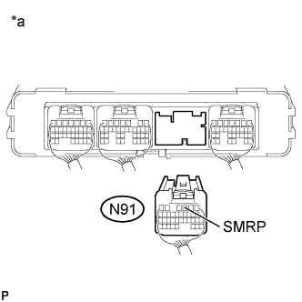
Text in Illustration *a Rear view of wire harness connector
(to Power Management Control ECU)
Measure the resistance according to the value(s) in the table below.
Standard Resistance Tester Connection Switch Condition Specified Condition N91-3 (SMRP) - Body ground Power switch off 141 to 212 Ω -
Reconnect the N91 power management control ECU connector.
NG
CHECK HARNESS AND CONNECTOR (NO. 2 HYBRID BATTERY PACK WIRE CONNECTOR - POWER MANAGEMENT CONTROL ECU) Click here
OK
-
-
CHECK HARNESS AND CONNECTOR (SHORT TO POWER SUPPLY WIRES)
CAUTION:
Be sure to wear insulated gloves.
-
Check that the service plug grip is not installed.
Note
After removing the service plug grip, do not turn the power switch on (READY), unless instructed by the repair manual because this may cause a malfunction.
-
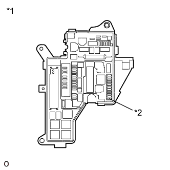
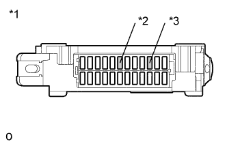
Text in Illustration *1 No. 1 Engine Room Relay Block and Junction Block Assembly *2 IGCT NO. 5 Fuse Remove the IGCT NO. 5 fuse from the No. 1 engine room relay block and junction block assembly.
-
for LHD:
-
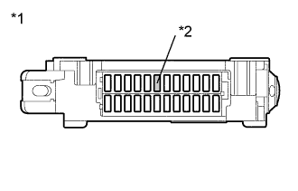
Text in Illustration *1 Cowl Side Junction Block LH *2 LH-IG2 Fuse Remove the LH-IG2 fuse from the cowl side junction block LH.
-
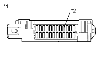
Text in Illustration *1 Cowl Side Junction Block RH *2 AM2 Fuse Remove the AM2 fuse from the cowl side junction block RH.
-
-
for RHD:
-
Text in Illustration *1 Cowl Side Junction Block LH *2 LH-IG2 Fuse *3 AM2 Fuse Remove the LH-IG2 fuse and AM2 fuse from the cowl side junction block LH.
-
-
Remove the upper hybrid battery cover subassembly Click here.
-
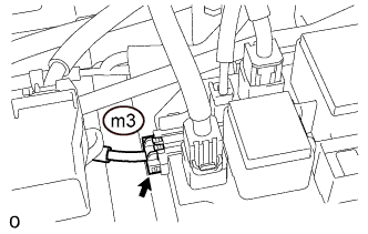
Disconnect the m3 hybrid battery junction block assembly connector.
-
Disconnect the A35, A36, N91 and N92 power management control ECU connectors.
-
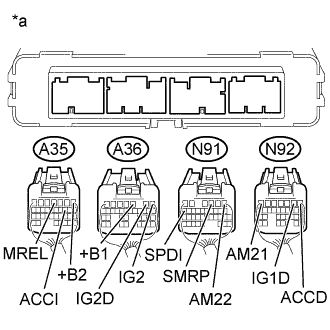
Text in Illustration *a Rear view of wire harness connector
(to Power Management Control ECU)
Measure the resistance according to the value(s) in the table below.
Standard Resistance Tester Connection Switch Condition Specified Condition N91-3 (SMRP) - A35-1 (+B2) Power switch off 10 kΩ or higher N91-3 (SMRP) - A36-3 (+B1) Power switch off 10 kΩ or higher N91-3 (SMRP) - N91-1 (AM22) Power switch off 10 kΩ or higher N91-3 (SMRP) - N92-7 (AM21) Power switch off 10 kΩ or higher N91-3 (SMRP) - A35-4 (MREL) Power switch off 10 kΩ or higher N91-3 (SMRP) - A36-1 (IG2) Power switch off 10 kΩ or higher N91-3 (SMRP) - N92-1 (ACCD) Power switch off 10 kΩ or higher N91-3 (SMRP) - A35-10 (ACCI) Power switch off 10 kΩ or higher N91-3 (SMRP) - N92-2 (IG1D) Power switch off 10 kΩ or higher N91-3 (SMRP) - A36-2 (IG2D) Power switch off 10 kΩ or higher N91-3 (SMRP) - N91-16 (SPDI) Power switch off 10 kΩ or higher -
Reconnect the A35, A36, N91 and N92 power management control ECU connectors.
-
Reconnect the m3 hybrid battery junction block assembly connector.
-
Install the upper hybrid battery cover sub-assembly.
-
Install the LH-IG2 fuse, AM2 fuse and IGCT NO. 5 fuse.
NG
REPAIR OR REPLACE HARNESS OR CONNECTOR
OK
REPLACE POWER MANAGEMENT CONTROL ECU Click here
-
-
CHECK HARNESS AND CONNECTOR (NO. 2 HYBRID BATTERY PACK WIRE CONNECTOR - POWER MANAGEMENT CONTROL ECU)
CAUTION:
Be sure to wear insulated gloves.
-
Check that the service plug grip is not installed.
Note
After removing the service plug grip, do not turn the power switch on (READY), unless instructed by the repair manual because this may cause a malfunction.
-
Remove the front luggage compartment trim cover Click here.
-
Disconnect the mT1 No. 2 hybrid battery pack wire connector.
-
Disconnect the N91 power management control ECU connector.
-
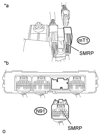
Text in Illustration *a Rear view of wire harness connector
(to No. 2 Hybrid Battery Pack Wire Connector)
*b Rear view of wire harness connector
(to Power Management Control ECU)
Measure the resistance according to the value(s) in the table below.
Standard Resistance (Check for Open) Tester Connection Switch Condition Specified Condition mT1-2 (SMRP) - N91-3 (SMRP) Power switch off Below 1 Ω Standard Resistance (Check for Short) Tester Connection Switch Condition Specified Condition mT1-2 (SMRP) and N91-3 (SMRP) - Body ground and other terminals Power switch off 10 kΩ or higher -
Reconnect the N91 power management control ECU connector.
-
Reconnect the mT1 No. 2 hybrid battery pack wire connector.
-
Install the front luggage compartment trim cover.
NG
REPAIR OR REPLACE HARNESS OR CONNECTOR
OK
-
-
CHECK HARNESS AND CONNECTOR (NO. 2 HYBRID BATTERY PACK WIRE CONNECTOR - HYBRID BATTERY JUNCTION BLOCK ASSEMBLY)
CAUTION:
Be sure to wear insulated gloves.
-
Check that the service plug grip is not installed.
Note
After removing the service plug grip, do not turn the power switch on (READY), unless instructed by the repair manual because this may cause a malfunction.
-
Remove the front luggage compartment trim cover Click here.
-
Disconnect the mT1 No. 2 hybrid battery pack wire connector.
-
Remove the upper hybrid battery cover sub-assembly Click here.
-
Disconnect the m3 hybrid battery junction block assembly connector.
-
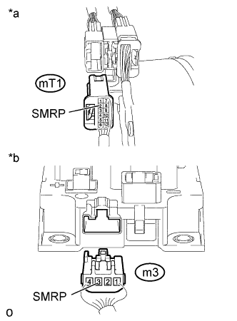
Text in Illustration *a Rear view of wire harness connector
(to No. 2 Hybrid Battery Pack Wire Connector)
*b Rear view of wire harness connector
(to Power Management Control ECU)
Measure the resistance according to the value(s) in the table below.
Standard Resistance (Check for Open) Tester Connection Switch Condition Specified Condition mT1-2 (SMRP) - m3-3 (SMRP) Power switch off Below 1 Ω Standard Resistance (Check for Short) Tester Connection Switch Condition Specified Condition mT1-2 (SMRP) and m3-3 (SMRP) - Body ground and other terminals Power switch off 10 kΩ or higher -
Reconnect the m3 hybrid battery junction block assembly connector.
-
Install the upper hybrid battery cover sub-assembly.
-
Reconnect the mT1 No. 2 hybrid battery pack wire connector.
-
Install the front luggage compartment trim cover.
NG
REPAIR OR REPLACE HARNESS OR CONNECTOR
OK
-
-
CHECK HARNESS AND CONNECTOR (HYBRID BATTERY JUNCTION BLOCK ASSEMBLY - BODY GROUND)
CAUTION:
Be sure to wear insulated gloves.
-
Check that the service plug grip is not installed.
Note
After removing the service plug grip, do not turn the power switch on (READY), unless instructed by the repair manual because this may cause a malfunction.
-
Remove the upper hybrid battery cover sub-assembly Click here.
-
Disconnect the m3 hybrid battery junction block assembly connector.
-
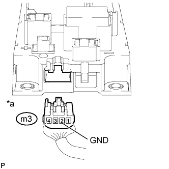
Text in Illustration *a Rear view of wire harness connector
(to Hybrid Battery Junction Block Assembly)
Measure the resistance according to the value(s) in the table below.
Standard Resistance Tester Connection Switch Condition Specified Condition m3-2 (GND) - Body ground Power switch off Below 1 Ω -
Reconnect the m3 hybrid battery junction block assembly connector.
-
Install the upper hybrid battery cover sub-assembly.
NG
REPAIR OR REPLACE HARNESS OR CONNECTOR
OK
-
-
INSPECT HYBRID BATTERY JUNCTION BLOCK ASSEMBLY (SMRP)
CAUTION:
Be sure to wear insulated gloves.
-
Check that the service plug grip is not installed.
Note
After removing the service plug grip, do not turn the power switch on (READY), unless instructed by the repair manual because this may cause a malfunction.
-
Remove the hybrid battery junction block assembly Click here.
-
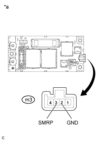
Text in Illustration *a Component without harness connected
(Hybrid Battery Junction Block Assembly)
Measure the resistance according to the value(s) in the table below.
Standard Resistance Tester Connection Condition Specified Condition m3-3 (SMRP) - m3-2 (GND) -40 to 80°C (-40 to 176°F) 112 to 274 Ω -
Install the hybrid battery junction block assembly.
NG
REPLACE HYBRID BATTERY JUNCTION BLOCK ASSEMBLY Click here
OK
CHECK FOR INTERMITTENT PROBLEMS Click here
-