СИСТЕМА УПРАВЛЕНИЯ ГИБРИДНОЙ СИСТЕМОЙ, Diagnostic DTC:P0A78-286
| DTC Code | DTC Name |
|---|---|
| P0A78-286 | Drive Motor "A" Inverter Performance |
DESCRIPTION
For a description of the inverter Click here.
If the motor inverter overheats, has a circuit malfunction, or has an internal short, the inverter transmits this information to the MG ECU via the motor inverter fail signal line.
Tech Tips
The term "drive motor A" indicates motor (MG2).
| DTC No. | DTC Detection Condition | Trouble Area |
|---|---|---|
| P0A78-286 | Motor inverter fail signal detection (circuit malfunction) (1 trip detection logic) |
|
WIRING DIAGRAM
Refer to the wiring diagram for DTC P0A1A-200 Click here.
Refer to the wiring diagram for DTC P0AA6-526 Click here.
Refer to the wiring diagram for DTC P324E-788 Click here.
Refer to the wiring diagram for DTC U0110-159 Click here.
INSPECTION PROCEDURE
CAUTION:
-
Before inspecting the high-voltage system or disconnecting the low voltage connector of the inverter with converter assembly, take safety precautions such as wearing insulated gloves and removing the service plug grip to prevent electrical shocks. After removing the service plug grip, put it in your pocket to prevent other technicians from accidentally reconnecting it while you are working on the high-voltage system.
-
After removing the service plug grip, wait for at least 10 minutes before touching any of the high-voltage connectors or terminals. After waiting for 10 minutes, check the voltage at the terminals in the inspection point in the inverter with converter assembly. The voltage should be 0 V before beginning work Click here.
Tech Tips
Waiting for at least 10 minutes is required to discharge the high-voltage capacitor inside the inverter with converter assembly.
Note
-
After turning the power switch off, waiting time may be required before disconnecting the cable from the negative (-) auxiliary battery terminal. Therefore, make sure to read the disconnecting the cable from the negative (-) auxiliary battery terminal notices before proceeding with work Click here.
-
After troubleshooting and repairing all output DTCs, be sure to replace the inverter with converter assembly. (The inverter with converter assembly may have been broken or damaged due to a circuit malfunction.)
Tech Tips
After the repair, clear the DTCs and perform the following procedure to check that DTCs are not output.
-
Turn the power switch on (READY) and wait for 10 seconds or more.
-
Perform a road test according to the freeze frame data "Vehicle Spd" for approximately 10 minutes.
PROCEDURE
-
CHECK DTC OUTPUT (HYBRID CONTROL)
-
Connect the GTS to the DLC3.
-
Turn the power switch on (IG).
-
Enter the following menus: Powertrain / Hybrid Control / Trouble Codes.
-
Check for DTCs.
Result Result Proceed to P0A78-202 is not output. A P0A78-202 is also output. B Note
-
If P0A78-202 is output, troubleshoot it first. After completing the troubleshooting for P0A78-202, perform troubleshooting for this DTC.
-
Parts repaired or replaced during troubleshooting for P0A78-202 do not need to be re-inspected in this diagnosis procedure.
-
-
Turn the power switch off.
B 
GO TO DTC CHART (P0A78-202) Click here
A 
-
-
CHECK DTC OUTPUT (HYBRID CONTROL)
-
Connect the GTS to the DLC3.
-
Turn the power switch on (IG).
-
Enter the following menus: Powertrain / Hybrid Control / Trouble Codes.
-
Check for DTCs.
Tech Tips
-
If P0A78-202 was not output in step 1 of this diagnosis procedure, check Table 1 below.
-
If P0A78-202 was output in step 1 of this diagnosis procedure, diagnose that DTC first, then check Table 2 below.
Result Result Proceed to P0A78-286 only is output, or DTCs except the ones in the tables below are also output. A Any of the following DTCs are also output. B Table 1 Relevant DTC P0A1A (all INF codes)*1 Generator Control Module P0A1B (all INF codes)*1 Drive Motor "A" Control Module P0A1D (all INF codes)*1 Hybrid Powertrain Control Module P0A3F-243 Drive Motor "A" Position Sensor Circuit P0A40-500 Drive Motor "A" Position Sensor Circuit Range / Performance P0A41-245 Drive Motor "A" Position Sensor Circuit Low P0A4B-253 Generator Position Sensor Circuit P0A4C-513 Generator Position Sensor Circuit Range / Performance P0A4D-255 Generator Position Sensor Circuit Low P0A60 (all INF codes)*1 Drive Motor "A" Phase V Current P0A63 (all INF codes)*1 Drive Motor "A" Phase W Current P0A72 (all INF codes)*1 Generator Phase V Current P0A75 (all INF codes)*1 Generator Phase W Current P0A78-113, 128, 266, 267, 279, 284, 287, 306, 503, 504, 505, 506, 586, 806, 807, 808 Drive Motor "A" Inverter Performance P0A7A-122, 130, 322, 325, 344, 517, 518, 809, 810, 811 Generator Inverter Performance P0A90-509 Drive Motor "A" Performance P0A92-521 Hybrid Generator Performance P0A94-442, 547, 548, 549, 554, 555, 556, 585, 587, 589, 590 DC / DC Converter Performance P0C73-776 Motor Electronics Coolant Pump "A" Control Performance P0C76-523 Hybrid Battery System Discharge Time Too Long P314A-828 Inverter Coolant Pump Speed Signal Table 2 Relevant DTC P0A1A (all INF codes)*1 Generator Control Module P0A1B (all INF codes)*1 Drive Motor "A" Control Module P0A1D (all INF codes)*1 Hybrid Powertrain Control Module P0A3F-243 Drive Motor "A" Position Sensor Circuit P0A40-500 Drive Motor "A" Position Sensor Circuit Range / Performance P0A41-245 Drive Motor "A" Position Sensor Circuit Low P0A4B-253 Generator Position Sensor Circuit P0A4C-513 Generator Position Sensor Circuit Range / Performance P0A4D-255 Generator Position Sensor Circuit Low P0A60-294 Drive Motor "A" Phase V Current P0A63-302 Drive Motor "A" Phase W Current P0A72 (all INF codes)*1 Generator Phase V Current P0A75 (all INF codes)*1 Generator Phase W Current P0A78-113, 128, 266, 267, 279, 284, 287, 503, 504, 505, 506, 586, 806, 807, 808 Drive Motor "A" Inverter Performance P0A7A-122, 130, 322, 325, 344, 517, 518, 809, 810, 811 Generator Inverter Performance P0A92-521 Hybrid Generator Performance P0A94-442, 547, 548, 549, 554, 555, 556, 585, 587, 589, 590 DC / DC Converter Performance P0C73-776 Motor Electronics Coolant Pump "A" Control Performance P0C76-523 Hybrid Battery System Discharge Time Too Long P314A-828 Inverter Coolant Pump Speed Signal Tech Tips
-
*1: If any INF codes are output for this DTC, refer to the corresponding diagnostic procedure.
-
P0A78-286 may be stored due to a malfunction which also causes DTCs in the preceding tables to be stored. In this case, first troubleshoot the output DTCs in the preceding tables. After troubleshooting and repairing all output DTCs, be sure to replace the inverter with converter assembly.
-
-
Turn the power switch off.
B
GO TO DTC CHART (HYBRID CONTROL SYSTEM) Click here
A
-
-
CHECK CONNECTOR CONNECTION CONDITION (INVERTER WITH CONVERTER ASSEMBLY CONNECTOR)
CAUTION:
Be sure to wear insulated gloves.
-
Check that the service plug grip is not installed.
Note
After removing the service plug grip, do not turn the power switch on (READY), unless instructed by the repair manual because this may cause a malfunction.
-
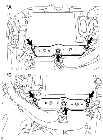
Check connection condition of the low voltage connector of the inverter with converter assembly and the contact pressure of each terminal. Check the terminals for deformation, and check the connector for water ingress and foreign matter Click here.
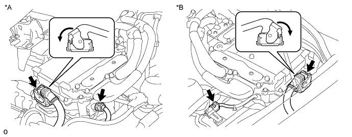
Text in Illustration *A for LHD *B for RHD Note
Before disconnecting the connector, confirm that it is properly connected by checking that the locking claws are engaged and that the connector does not pull out.
OK - The connector is connected securely. - The terminals are not deformed and are connected securely. - No water or foreign matter in the connector. Result Result Proceed to OK A NG (The connector is not connected securely.) B NG (The terminals are not making secure contact or are deformed, or water or foreign matter exists in the connector.) C Tech Tips
When connecting the connector, insert it with the locking lever in the raised position. Rotate the lever downward and make sure that the connector is pulled into its socket. When the locking lever is in its fully closed position, a click will be heard as its locking claws engage. After the click is heard, pull up on the connector to confirm that it is properly connected.
B
CONNECT SECURELY
C
REPAIR OR REPLACE HARNESS OR CONNECTOR
A
-
-
CHECK QUANTITY OF HV COOLANT
-
Проверьте уровень охлаждающей жидкости гибридной системы в расширительном бачке инвертора.
-
Проверьте, нет ли утечек охлаждающей жидкости гибридной системы.
Результат Результат Перейти к Утечки не обнаружены, и уровень охлаждающей жидкости в расширительном бачке инвертора выше нижней отметки. А Утечки не обнаружены, и уровень охлаждающей жидкости в расширительном бачке инвертора ниже нижней отметки. B Обнаружены утечки охлаждающей жидкости гибридной системы. C Note
Насос системы охлаждения инвертора с электродвигателем в сборе имеет функцию защиты, которая активируется в случае утечки охлаждающей жидкости гибридной системы. Таким образом, нет необходимости заменять насос системы охлаждения инвертора с электродвигателем в сборе, если только причиной утечки охлаждающей жидкости гибридной системы не является насос системы охлаждения инвертора с электродвигателем в сборе.
Tech Tips
После устранения утечек и добавления охлаждающей жидкости гибридной системы выполните испытания Active Test "Activate the (Inverter) Water Pump" (включение насоса системы охлаждения инвертора) (испытание из раздела HV) и "Control the Electric Cooling Fan" (управление электрическим вентилятором системы охлаждения) (испытание из раздела Engine), и убедитесь в отсутствии неисправностей.
B
ADD HV COOLANT
C
INSPECT FOR HV COOLANT LEAK AND ADD HV COOLANT
A
-
-
CHECK COOLANT HOSE
-
Убедитесь, что шланги системы охлаждения не перегнуты и не засорены.
NG
REPAIR OR REPLACE COOLANT HOSE
OK
-
-
PERFORM ACTIVE TEST USING GTS (CONTROL THE ELECTRIC COOLING FAN)
-
Подключите GTS к DLC3.
-
Включите питание (IG).
-
Войдите в следующие меню: Powertrain / Engine and ECT / Active Test / Control the Electric Cooling Fan.
-
Выполните испытание Active Test "Control the Electric Cooling Fan" (управление электрическим вентилятором системы охлаждения).
OK Вентилятор системы охлаждения вращается. -
Выключите питание.
NG
CHECK COOLING FAN SYSTEM Click here
OK
-
-
CHECK HV COOLANT (CHECK FOR CONDITIONS THAT MAY HAVE CAUSED FREEZING)
-
Connect the GTS to the DLC3.
-
Turn the power switch on (IG).
-
Enter the following menus: Powertrain / Hybrid Control / Trouble Codes.
-
Read the freeze frame data item Ambient Temperature using the GTS.
-
Check if the freeze frame data item Ambient Temperature is below the freezing temperature of the HV coolant.
Result Result Proceed to Ambient Temperature value is above freezing temperature of the HV coolant. A Ambient Temperature value is below freezing temperature of the HV coolant. B Tech Tips
-
HV coolant (SLLC) with a 30% concentration freezes at -15°C (5°F) and HV coolant (SLLC) with a 50% concentration freezes at -35°C (-31°F).
-
If the HV coolant freezes in the HV radiator or HV water pump, the coolant temperature in the inverter with converter assembly rises because the HV coolant cannot circulate. As a result, a DTC may be stored.
-
A DTC is stored when the water pump impeller cannot rotate due to freezing of the HV coolant.
-
If a DTC is stored due to freezing of HV coolant, the problem cannot be reproduced. Judge whether freezing of HV coolant occurred according to the freeze point of the HV coolant, HV coolant change history and ambient temperature when the DTC was stored.
-
-
Turn the power switch off.
B 
A
-
-
CHECK HARNESS AND CONNECTOR (INVERTER WITH CONVERTER ASSEMBLY - GENERATOR RESOLVER)
CAUTION:
Be sure to wear insulated gloves.
-
Check that the service plug grip is not installed.
Note
After removing the service plug grip, do not turn the power switch on (READY), unless instructed by the repair manual because this may cause a malfunction.
-
Disconnect the A38*1 or A74*2 inverter with converter assembly connector.
-
*1: for LHD
-
*2: for RHD
-
-
Connect the cable to the negative (-) auxiliary battery terminal.
-
Turn the power switch on (IG).
-
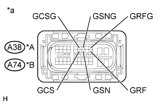
Text in Illustration *A for LHD *B for RHD *a Front view of wire harness connector
(to Inverter with Converter Assembly)
Measure the voltage according to the value(s) in the table below.
Standard Voltage for LHD Tester Connection Switch Condition Specified Condition A38-20 (GRF) - Body ground Power switch on (IG) Below 1 V A38-9 (GRFG) - Body ground Power switch on (IG) Below 1 V A38-18 (GSN) - Body ground Power switch on (IG) Below 1 V A38-7 (GSNG) - Body ground Power switch on (IG) Below 1 V A38-17 (GCS) - Body ground Power switch on (IG) Below 1 V A38-6 (GCSG) - Body ground Power switch on (IG) Below 1 V for RHD Tester Connection Switch Condition Specified Condition A74-20 (GRF) - Body ground Power switch on (IG) Below 1 V A74-9 (GRFG) - Body ground Power switch on (IG) Below 1 V A74-18 (GSN) - Body ground Power switch on (IG) Below 1 V A74-7 (GSNG) - Body ground Power switch on (IG) Below 1 V A74-17 (GCS) - Body ground Power switch on (IG) Below 1 V A74-6 (GCSG) - Body ground Power switch on (IG) Below 1 V Note
Turning the power switch on (IG) with the inverter with converter assembly disconnected causes other DTCs to be stored. Clear the DTCs after performing this inspection.
-
Turn the power switch off.
-
Disconnect the cable from the negative (-) auxiliary battery terminal.
-
Reconnect the A38*1 or A74*2 inverter with converter assembly connector.
-
*1: for LHD
-
*2: for RHD
-
NG
REPAIR OR REPLACE HARNESS OR CONNECTOR
OK
-
-
CHECK GENERATOR RESOLVER
CAUTION:
Be sure to wear insulated gloves.
-
Check that the service plug grip is not installed.
Note
After removing the service plug grip, do not turn the power switch on (READY), unless instructed by the repair manual because this may cause a malfunction.
-
Disconnect the A38*1 or A74*2 inverter with converter assembly connector.
-
*1: for LHD
-
*2: for RHD
-
-
Text in Illustration *A for LHD *B for RHD *a Front view of wire harness connector
(to Inverter with Converter Assembly)
Measure the resistance according to the value(s) in the table below.
Standard Resistance (Check for Open) for LHD Tester Connection Switch Condition Specified Condition A38-20 (GRF) - A38-9 (GRFG) Power switch off 4.2 to 12.5 Ω A38-18 (GSN) - A38-7 (GSNG) Power switch off 9.8 to 20.1 Ω A38-17 (GCS) - A38-6 (GCSG) Power switch off 9.8 to 20.1 Ω for RHD Tester Connection Switch Condition Specified Condition A74-20 (GRF) - A74-9 (GRFG) Power switch off 4.2 to 12.5 Ω A74-18 (GSN) - A74-7 (GSNG) Power switch off 9.8 to 20.1 Ω A74-17 (GCS) - A74-6 (GCSG) Power switch off 9.8 to 20.1 Ω Standard Resistance (Check for Short) for LHD Tester Connection Switch Condition Specified Condition A38-20 (GRF) or A38-9 (GRFG) - Body ground and other terminals Power switch off 1 MΩ or higher A38-18 (GSN) or A38-7 (GSNG) - Body ground and other terminals Power switch off 1 MΩ or higher A38-17 (GCS) or A38-6 (GCSG) - Body ground and other terminals Power switch off 1 MΩ or higher for RHD Tester Connection Switch Condition Specified Condition A74-20 (GRF) or A74-9 (GRFG) - Body ground and other terminals Power switch off 1 MΩ or higher A74-18 (GSN) or A74-7 (GSNG) - Body ground and other terminals Power switch off 1 MΩ or higher A74-17 (GCS) or A74-6 (GCSG) - Body ground and other terminals Power switch off 1 MΩ or higher -
Reconnect the A38*1 or A74*2 inverter with converter assembly connector.
-
*1: for LHD
-
*2: for RHD
-
NG
OK
-
-
CHECK HARNESS AND CONNECTOR (INVERTER WITH CONVERTER ASSEMBLY - MOTOR RESOLVER)
CAUTION:
Be sure to wear insulated gloves.
-
Check that the service plug grip is not installed.
Note
After removing the service plug grip, do not turn the power switch on (READY), unless instructed by the repair manual because this may cause a malfunction.
-
Disconnect the A38*1 or A74*2 inverter with converter assembly connector.
-
*1: for LHD
-
*2: for RHD
-
-
Connect the cable to the negative (-) auxiliary battery terminal.
-
Turn the power switch on (IG).
-
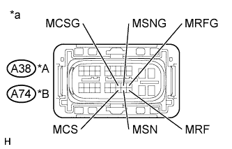
Text in Illustration *A for LHD *B for RHD *a Front view of wire harness connector
(to Inverter with Converter Assembly)
Measure the voltage according to the value(s) in the table below.
Standard Voltage for LHD Tester Connection Switch Condition Specified Condition A38-40 (MRF) - Body ground Power switch on (IG) Below 1 V A38-29 (MRFG) - Body ground Power switch on (IG) Below 1 V A38-39 (MSN) - Body ground Power switch on (IG) Below 1 V A38-28 (MSNG) - Body ground Power switch on (IG) Below 1 V A38-38 (MCS) - Body ground Power switch on (IG) Below 1 V A38-27 (MCSG) - Body ground Power switch on (IG) Below 1 V for RHD Tester Connection Switch Condition Specified Condition A74-40 (MRF) - Body ground Power switch on (IG) Below 1 V A74-29 (MRFG) - Body ground Power switch on (IG) Below 1 V A74-39 (MSN) - Body ground Power switch on (IG) Below 1 V A74-28 (MSNG) - Body ground Power switch on (IG) Below 1 V A74-38 (MCS) - Body ground Power switch on (IG) Below 1 V A74-27 (MCSG) - Body ground Power switch on (IG) Below 1 V Note
Turning the power switch on (IG) with the inverter with converter assembly disconnected causes other DTCs to be stored. Clear the DTCs after performing this inspection.
-
Turn the power switch off.
-
Disconnect the cable from the negative (-) auxiliary battery terminal.
-
Reconnect the A38*1 or A74*2 inverter with converter assembly connector.
-
*1: for LHD
-
*2: for RHD
-
NG
REPAIR OR REPLACE HARNESS OR CONNECTOR
OK
-
-
CHECK MOTOR RESOLVER
CAUTION:
Be sure to wear insulated gloves.
-
Check that the service plug grip is not installed.
Note
After removing the service plug grip, do not turn the power switch on (READY), unless instructed by the repair manual because this may cause a malfunction.
-
Disconnect the A38*1 or A74*2 inverter with converter assembly connector.
-
*1: for LHD
-
*2: for RHD
-
-
Text in Illustration *A for LHD *B for RHD *a Front view of wire harness connector
(to Inverter with Converter Assembly)
Measure the resistance according to the value(s) in the table below.
Standard Resistance (Check for Open) for LHD Tester Connection Switch Condition Specified Condition A38-40 (MRF) - A38-29 (MRFG) Power switch off 4.2 to 12.5 Ω A38-39 (MSN) - A38-28 (MSNG) Power switch off 9.8 to 20.1 Ω A38-38 (MCS) - A38-27 (MCSG) Power switch off 9.8 to 20.1 Ω for RHD Tester Connection Switch Condition Specified Condition A74-40 (MRF) - A74-29 (MRFG) Power switch off 4.2 to 12.5 Ω A74-39 (MSN) - A74-28 (MSNG) Power switch off 9.8 to 20.1 Ω A74-38 (MCS) - A74-27 (MCSG) Power switch off 9.8 to 20.1 Ω Standard Resistance (Check for Short) for LHD Tester Connection Switch Condition Specified Condition A38-40 (MRF) or A38-29 (MRFG) - Body ground and other terminals Power switch off 1 MΩ or higher A38-39 (MSN) or A38-28 (MSNG) - Body ground and other terminals Power switch off 1 MΩ or higher A38-38 (MCS) or A38-27 (MCSG) - Body ground and other terminals Power switch off 1 MΩ or higher for RHD Tester Connection Switch Condition Specified Condition A74-40 (MRF) or A74-29 (MRFG) - Body ground and other terminals Power switch off 1 MΩ or higher A74-39 (MSN) or A74-28 (MSNG) - Body ground and other terminals Power switch off 1 MΩ or higher A74-38 (MCS) or A74-27 (MCSG) - Body ground and other terminal Power switch off 1 MΩ or higher -
Reconnect the A38*1 or A74*2 inverter with converter assembly connector.
-
*1: for LHD
-
*2: for RHD
-
NG
OK
-
-
CHECK INVERTER WITH CONVERTER ASSEMBLY (GENERATOR CABLE CONNECTION CONDITION)
CAUTION:
Be sure to wear insulated gloves.
-
Check that the service plug grip is not installed.
Note
After removing the service plug grip, do not turn the power switch on (READY), unless instructed by the repair manual because this may cause a malfunction.
-
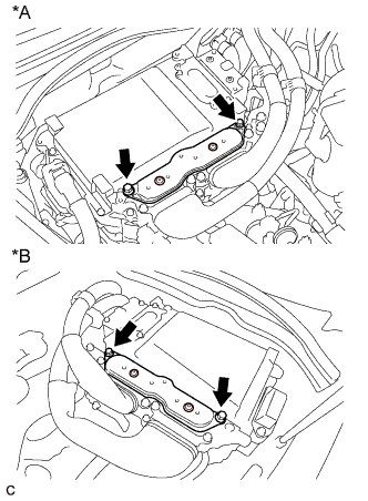
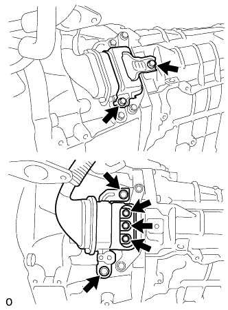
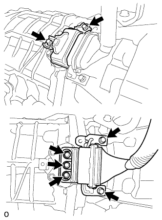
Text in Illustration *A for LHD *B for RHD for Type A:
-
Remove the inverter terminal cover from the inverter with converter assembly.
-
-
Text in Illustration *A for LHD *B for RHD for Type B:
-
Remove the inverter terminal cover from the inverter with converter assembly.
-
-
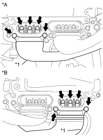
Text in Illustration *A for LHD *B for RHD *1 Generator Cable
(Inverter with Converter Assembly Side)
Check that the bolts for the generator cable are tightened to the specified torque, the generator cable is connected
Specified Condition T=8.0 N*m (82 kgf*cm, 71 in.*lbf) Note
Make sure that the tightening torque of the bolt is between 6.4 and 9.6 N*m (65 and 98 kgf*cm, 57 and 85 in.*lbf).
-
Disconnect the generator cable from the inverter with converter assembly.
-
Check for arc marks at the terminals for the generator cable.
Result Result Proceed to The terminals are connected securely and there are no contact problems. There are no arc marks. A The terminals are not connected securely and there is a contact problem. There are arc marks. B The terminals are not connected securely and there is a contact problem. There are no arc marks. C The terminals are connected securely and there are no contact problems. There are arc marks. B -
Connect the generator cable to the inverter with converter assembly.
-
Install the inverter terminal cover.
B
REPLACE MALFUNCTIONING PARTS
C
CONNECT SECURELY
A
-
-
CHECK INVERTER WITH CONVERTER ASSEMBLY (MOTOR CABLE CONNECTION CONDITION)
CAUTION:
Be sure to wear insulated gloves.
-
Check that the service plug grip is not installed.
Note
After removing the service plug grip, do not turn the power switch on (READY), unless instructed by the repair manual because this may cause a malfunction.
-
Text in Illustration *A for LHD *B for RHD for Type A:
-
Remove the inverter terminal cover from the inverter with converter assembly.
-
-
Text in Illustration *A for LHD *B for RHD for Type B:
-
Remove the inverter terminal cover from the inverter with converter assembly.
-
-
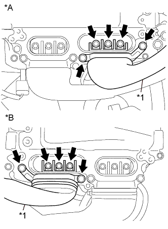
Text in Illustration *A for LHD *B for RHD *1 Motor Cable
(Inverter with Converter Assembly Side)
Check that the bolts for the motor cable are tightened to the specified torque, the motor cable is connected securely, and there are no contact problems.
Specified Condition T=8.0 N*m (82 kgf*cm, 71 in.*lbf) Note
Make sure that the tightening torque of the bolt is between 6.4 and 9.6 N*m (65 and 98 kgf*cm, 57 and 85 in.*lbf).
-
Disconnect the motor cable from the inverter with converter assembly.
-
Check for arc marks at the terminals for the motor cable.
Result Result Proceed to The terminals are connected securely and there are no contact problems. There are no arc marks. A The terminals are not connected securely and there is a contact problem. There are arc marks. B The terminals are not connected securely and there is a contact problem. There are no arc marks. C The terminals are connected securely and there are no contact problems. There are arc marks. B -
Connect the motor cable to the inverter with converter assembly.
-
Install the inverter terminal cover.
B
REPLACE MALFUNCTIONING PARTS
C
CONNECT SECURELY
A
-
-
CHECK HYBRID VEHICLE TRANSMISSION ASSEMBLY (MG1)
CAUTION:
Be sure to wear insulated gloves.
-
Check that the service plug grip is not installed.
Note
After removing the service plug grip, do not turn the power switch on (READY), unless instructed by the repair manual because this may cause a malfunction.
-
Text in Illustration *A for LHD *B for RHD for Type A:
-
Remove the inverter terminal cover from the inverter with converter assembly.
-
-
Text in Illustration *A for LHD *B for RHD for Type B:
-
Remove the inverter terminal cover from the inverter with converter assembly.
-
-
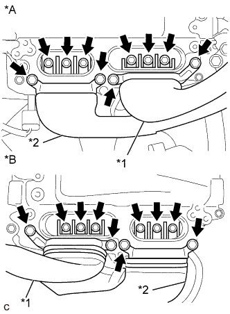
Text in Illustration *A for LHD *B for RHD *1 Motor Cable *2 Generator Cable Disconnect the generator cable and motor cable from the inverter with converter assembly.
-
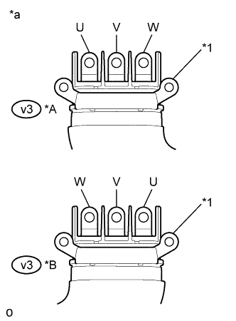
Text in Illustration *A for LHD *B for RHD *1 Shield Ground *a Generator Cable
(Inverter with Converter Assembly Side)
Check generator (MG1) for an interphase short using a milliohmmeter.
-
Using a milliohmmeter, measure the resistance according to the value(s) in the table below.
Tech Tips
If the generator (MG1) temperature is high, the resistance will vary greatly from the specification. Therefore, measure the resistance at least 8 hours after the vehicle is stopped.
Standard Resistance for LHD Tester Connection Switch Condition Specified Condition v3-3 (W) - v3-1 (U) Power switch off 59.2 to 65.2 mΩ v3-2 (V) - v3-3 (W) Power switch off 62.2 to 68.2 mΩ v3-1 (U) - v3-2 (V) Power switch off 59.2 to 65.2 mΩ for RHD Tester Connection Switch Condition Specified Condition v3-1 (W) - v3-3 (U) Power switch off 59.0 to 65.0 mΩ v3-2 (V) - v3-1 (W) Power switch off 61.9 to 67.9 mΩ v3-3 (U) - v3-2 (V) Power switch off 59.0 to 65.0 mΩ Tech Tips
To correct the variation of the measured resistance due to temperature, use the following formula to calculate the resistance at 20°C (68° F).
-
R20 = Rt / {1 + 0.00393 X (T - 20)}
The calculation is based on the following:
-
R20: Resistance at 20°C (68° F) (mΩ)
-
Rt: Measured resistance (mΩ)
-
T: Temperature when the resistance is measured (°C)
-
-
-
When checking for a short circuit between motor phases without using a milliohmmeter.
Note
The motor generates current when wheels are rotated by hand. Before performing the inspection, wrap the motor cable terminals with insulation tape.
Tech Tips
A short circuit between the motor phases can be checked simply without using a milliohmmeter.
-
Connect the cable to the negative (-) auxiliary battery terminal.
-
Turn the power switch on (IG).
Note
Turning the power switch on (IG) with the service plug grip removed causes other DTCs to be stored. Clear the DTCs after performing this inspection.
-
Move the shift lever to N.
-
Lift up the vehicle.
-
Rotate the rear wheels in the same direction simultaneously by hand.
Standard Left and right wheels rotate smoothly (No short circuit between phases) Tech Tips
If a short circuit exists between the motor phases, the rear wheels do not rotate smoothly (some resistance is felt).
-
Lower the vehicle.
-
Move the shift lever to P.
-
Turn the power switch off.
-
Disconnect the cable from the negative (-) auxiliary battery terminal.
-
-
Using a megohmmeter set to 500 V, measure the resistance according to the value(s) in the table below.
Note
Be sure to set the megohmmeter to 500 V when performing this test. Using a setting higher than 500 V can result in damage to the component being inspected.
Standard Resistance for LHD Tester Connection Switch Condition Specified Condition v3-3 (W) - Body ground and shield ground Power switch off 100 MΩ or higher v3-2 (V) - Body ground and shield ground Power switch off 100 MΩ or higher v3-1 (U) - Body ground and shield ground Power switch off 100 MΩ or higher for RHD Tester Connection Switch Condition Specified Condition v3-1 (W) - Body ground and shield ground Power switch off 100 MΩ or higher v3-2 (V) - Body ground and shield ground Power switch off 100 MΩ or higher v3-3 (U) - Body ground and shield ground Power switch off 100 MΩ or higher -
Measure the resistance according to the value(s) in the table below.
Tech Tips
Perform this procedure only when checking for a short circuit between motor phases without using a milliohmmeter.
Standard Resistance for LHD Tester Connection Switch Condition Specified Condition v3-3 (W) - v3-2 (V) Power switch off Below 1 Ω v3-2 (V) - v3-1 (U) Power switch off Below 1 Ω for RHD Tester Connection Switch Condition Specified Condition v3-1 (W) - v3-2 (V) Power switch off Below 1 Ω v3-2 (V) - v3-3 (U) Power switch off Below 1 Ω -
Connect the generator cable and motor cable.
-
Install the inverter terminal cover.
NG
OK
-
-
CHECK HYBRID VEHICLE TRANSMISSION ASSEMBLY (MG2)
CAUTION:
Be sure to wear insulated gloves.
-
Check that the service plug grip is not installed.
Note
After removing the service plug grip, do not turn the power switch on (READY), unless instructed by the repair manual because this may cause a malfunction.
-
Text in Illustration *A for LHD *B for RHD for Type A:
-
Remove the inverter terminal cover from the inverter with converter assembly.
-
-
Text in Illustration *A for LHD *B for RHD for Type B:
-
Remove the inverter terminal cover from the inverter with converter assembly.
-
-
Text in Illustration *A for LHD *B for RHD *1 Motor Cable *2 Generator Cable Disconnect the generator cable and motor cable from the inverter with converter assembly.
-
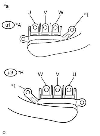
Text in Illustration *A for LHD *B for RHD *1 Shield Ground *a Motor Cable
(Inverter with Converter Assembly Side)
Check motor (MG2) for an interphase short using a milliohmmeter.
-
Using a milliohmmeter, measure the resistance according to the value(s) in the table below.
Tech Tips
If the motor (MG2) temperature is high, the resistance will vary greatly from the specification. Therefore, measure the resistance at least 8 hours after the vehicle is stopped.
Standard Resistance for LHD Tester Connection Switch Condition Specified Condition u1-3 (W) - u1-1 (U) Power switch off 47.0 to 51.8 mΩ u1-2 (V) - u1-3 (W) Power switch off 47.3 to 52.1 mΩ u1-1 (U) - u1-2 (V) Power switch off 47.1 to 51.9 mΩ for RHD Tester Connection Switch Condition Specified Condition u3-1 (W) - u3-3 (U) Power switch off 47.0 to 51.8 mΩ u3-2 (V) - u3-1 (W) Power switch off 47.3 to 52.1 mΩ u3-3 (U) - u3-2 (V) Power switch off 47.1 to 51.9 mΩ Tech Tips
To correct the variation of the measured resistance due to temperature, use the following formula to calculate the resistance at 20°C (68° F).
-
R20 = Rt / {1 + 0.00393 X (T - 20)}
The calculation is based on the following:
-
R20: Resistance at 20°C (68° F) (mΩ)
-
Rt: Measured resistance (mΩ)
-
T: Temperature when the resistance is measured (°C)
-
-
-
When checking for a short circuit between motor phases without using a milliohmmeter.
Note
The motor generates current when wheels are rotated by hand. Before performing the inspection, wrap the motor cable terminals with insulation tape.
Tech Tips
A short circuit between the motor phases can be checked simply without using a milliohmmeter.
-
Connect the cable to the negative (-) auxiliary battery terminal.
-
Turn the power switch on (IG).
Note
Turning the power switch on (IG) with the service plug grip removed causes other DTCs to be stored. Clear the DTCs after performing this inspection.
-
Move the shift lever to N.
-
Lift up the vehicle.
-
Rotate the rear wheels in the same direction simultaneously by hand.
Standard Left and right wheels rotate smoothly (No short circuit between phases) Tech Tips
If a short circuit exists between the motor phases, the rear wheels do not rotate smoothly (some resistance is felt).
-
Lower the vehicle.
-
Move the shift lever to P.
-
Turn the power switch off.
-
Disconnect the cable from the negative (-) auxiliary battery terminal.
-
-
Using a megohmmeter set to 500 V, measure the resistance according to the value(s) in the table below.
Note
Be sure to set the megohmmeter to 500 V when performing this test. Using a setting higher than 500 V can result in damage to the component being inspected.
Standard Resistance for LHD Tester Connection Switch Condition Specified Condition u1-3 (W) - Body ground and shield ground Power switch off 100 MΩ or higher u1-2 (V) - Body ground and shield ground Power switch off 100 MΩ or higher u1-1 (U) - Body ground and shield ground Power switch off 100 MΩ or higher for RHD Tester Connection Switch Condition Specified Condition u3-1 (W) - Body ground and shield ground Power switch off 100 MΩ or higher u3-2 (V) - Body ground and shield ground Power switch off 100 MΩ or higher u3-3 (U) - Body ground and shield ground Power switch off 100 MΩ or higher -
Measure the resistance according to the value(s) in the table below.
Tech Tips
Perform this procedure only when checking for a short circuit between motor phases without using a milliohmmeter.
Standard Resistance for LHD Tester Connection Switch Condition Specified Condition u1-3 (W) - u1-2 (V) Power switch off Below 1 Ω u1-2 (V) - u1-1 (U) Power switch off Below 1 Ω for RHD Tester Connection Switch Condition Specified Condition u3-1 (W) - u3-2 (V) Power switch off Below 1 Ω u3-2 (V) - u3-3 (U) Power switch off Below 1 Ω -
Connect the generator cable and motor cable.
-
Install the inverter terminal cover.
NG
OK
-
-
CHECK FUSE (IGCT NO. 4)
-
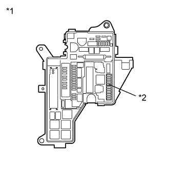
Text in Illustration *1 No. 1 Engine Room Relay Block and Junction Block Assembly *2 IGCT NO. 4 Fuse Remove the IGCT NO. 4 fuse from the No. 1 engine room relay block and junction block assembly.
-
Measure the resistance according to the value(s) in the table below.
Standard Resistance Tester Connection Condition Specified Condition IGCT NO. 4 fuse terminal Always Below 1 Ω -
Install the IGCT NO. 4 fuse.
NG
OK
-
-
CHECK HARNESS AND CONNECTOR (INVERTER WITH CONVERTER ASSEMBLY POWER SOURCE CIRCUIT)
CAUTION:
Be sure to wear insulated gloves.
-
Check that the service plug grip is not installed.
Note
After removing the service plug grip, do not turn the power switch on (READY), unless instructed by the repair manual because this may cause a malfunction.
-
Disconnect the A38*1 or A74*2 inverter with converter assembly connector.
-
*1: for LHD
-
*2: for RHD
-
-
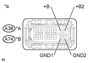
Text in Illustration *A for LHD *B for RHD *a Front view of wire harness connector
(to Inverter with Converter Assembly)
Measure the resistance according to the value(s) in the table below.
Standard Resistance for LHD Tester Connection Switch Condition Specified Condition A38-30 (GND1) - Body ground Power switch off Below 1 Ω A38-31 (GND2) - Body ground Power switch off Below 1 Ω for RHD Tester Connection Switch Condition Specified Condition A74-30 (GND1) - Body ground Power switch off Below 1 Ω A74-31 (GND2) - Body ground Power switch off Below 1 Ω -
Connect the cable to the negative (-) auxiliary battery terminal.
-
Turn the power switch on (IG).
-
Measure the voltage according to the value(s) in the table below.
Standard Voltage for LHD Tester Connection Switch Condition Specified Condition A38-10 (+B) - Body ground Power switch on (IG) Same as auxiliary battery voltage A38-11 (+B2) - Body ground Power switch on (IG) Same as auxiliary battery voltage for RHD Tester Connection Switch Condition Specified Condition A74-10 (+B) - Body ground Power switch on (IG) Same as auxiliary battery voltage A74-11 (+B2) - Body ground Power switch on (IG) Same as auxiliary battery voltage Note
Turning the power switch on (IG) with the inverter with converter assembly connector disconnected causes other DTCs to be stored. Clear the DTCs after performing this inspection.
-
Turn the power switch off.
-
Disconnect the cable from the negative (-) auxiliary battery terminal.
-
Reconnect the A38*1 or A74*2 inverter with converter assembly connector.
-
*1: for LHD
-
*2: for RHD
-
NG
REPAIR OR REPLACE POWER SOURCE CIRCUIT
OK
-
-
CHECK HARNESS AND CONNECTOR (POWER MANAGEMENT CONTROL ECU - INVERTER WITH CONVERTER ASSEMBLY)
CAUTION:
Be sure to wear insulated gloves.
-
Check that the service plug grip is not installed.
Note
After removing the service plug grip, do not turn the power switch on (READY), unless instructed by the repair manual because this may cause a malfunction.
-
Disconnect the A35 power management control ECU connector.
-
Disconnect the A38*1 or A74*2 inverter with converter assembly connector.
-
*1: for LHD
-
*2: for RHD
-
-
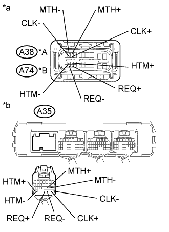
Text in Illustration *A for LHD *B for RHD *a Front view of wire harness connector
(to Inverter with Converter Assembly)
*b Rear view of wire harness connector
(to Power Management Control ECU)
Measure the resistance according to the value(s) in the table below.
Standard Resistance (Check for Open) for LHD Tester Connection Switch Condition Specified Condition A38-23 (HTM+) - A35-34 (HTM+) Power switch off Below 1 Ω A38-22 (HTM-) - A35-33 (HTM-) Power switch off Below 1 Ω A38-3 (MTH+) - A35-21 (MTH+) Power switch off Below 1 Ω A38-2 (MTH-) - A35-20 (MTH-) Power switch off Below 1 Ω A38-34 (REQ+) - A35-32 (REQ+) Power switch off Below 1 Ω A38-33 (REQ-) - A35-31 (REQ-) Power switch off Below 1 Ω A38-14 (CLK+) - A35-29 (CLK+) Power switch off Below 1 Ω A38-13 (CLK-) - A35-28 (CLK-) Power switch off Below 1 Ω for RHD Tester Connection Switch Condition Specified Condition A74-23 (HTM+) - A35-34 (HTM+) Power switch off Below 1 Ω A74-22 (HTM-) - A35-33 (HTM-) Power switch off Below 1 Ω A74-3 (MTH+) - A35-21 (MTH+) Power switch off Below 1 Ω A74-2 (MTH-) - A35-20 (MTH-) Power switch off Below 1 Ω A74-34 (REQ+) - A35-32 (REQ+) Power switch off Below 1 Ω A74-33 (REQ-) - A35-31 (REQ-) Power switch off Below 1 Ω A74-14 (CLK+) - A35-29 (CLK+) Power switch off Below 1 Ω A74-13 (CLK-) - A35-28 (CLK-) Power switch off Below 1 Ω Standard Resistance (Check for Short) for LHD Tester Connection Switch Condition Specified Condition A38-23 (HTM+) or A35-34 (HTM +) - Body ground and other terminals Power switch off 10 kΩ or higher A38-22 (HTM-) or A35-33 (HTM-) - Body ground and other terminals Power switch off 10 kΩ or higher A38-3 (MTH+) or A35-21 (MTH+) - Body ground and other terminals Power switch off 10 kΩ or higher A38-2 (MTH-) or A35-20 (MTH-) - Body ground and other terminals Power switch off 10 kΩ or higher A38-34 (REQ+) or A35-32 (REQ+) - Body ground and other terminals Power switch off 10 kΩ or higher A38-33 (REQ-) or A35-31 (REQ-) - Body ground and other terminals Power switch off 10 kΩ or higher A38-14 (CLK+) or A35-29 (CLK+) - Body ground and other terminals Power switch off 10 kΩ or higher A38-13 (CLK-) or A35-28 (CLK-) - Body ground and other terminals Power switch off 10 kΩ or higher for RHD Tester Connection Switch Condition Specified Condition A74-23 (HTM+) or A35-34 (HTM +) - Body ground and other terminals Power switch off 10 kΩ or higher A74-22 (HTM-) or A35-33 (HTM-) - Body ground and other terminals Power switch off 10 kΩ or higher A74-3 (MTH+) or A35-21 (MTH+) - Body ground and other terminals Power switch off 10 kΩ or higher A74-2 (MTH-) or A35-20 (MTH-) - Body ground and other terminals Power switch off 10 kΩ or higher A74-34 (REQ+) or A35-32 (REQ+) - Body ground and other terminals Power switch off 10 kΩ or higher A74-33 (REQ-) or A35-31 (REQ-) - Body ground and other terminals Power switch off 10 kΩ or higher A74-14 (CLK+) or A35-29 (CLK+) - Body ground and other terminals Power switch off 10 kΩ or higher A74-13 (CLK-) or A35-28 (CLK-) - Body ground and other terminals Power switch off 10 kΩ or higher -
Connect the cable to the negative (-) auxiliary battery terminal.
-
Turn the power switch on (IG).
-
Measure the voltage according to the value(s) in the table below.
Standard Voltage for LHD Tester Connection Switch Condition Specified Condition A38-23 (HTM+) or A35-34 (HTM+) - Body ground Power switch on (IG) Below 1 V A38-22 (HTM-) or A35-33 (HTM-) - Body ground Power switch on (IG) Below 1 V A38-3 (MTH+) or A35-21 (MTH+) - Body ground Power switch on (IG) Below 1 V A38-2 (MTH-) or A35-20 (MTH-) - Body ground Power switch on (IG) Below 1 V A38-34 (REQ+) or A35-32 (REQ+) - Body ground Power switch on (IG) Below 1 V A38-33 (REQ-) or A35-31 (REQ-) - Body ground Power switch on (IG) Below 1 V A38-14 (CLK+) or A35-29 (CLK+) - Body ground Power switch on (IG) Below 1 V A38-13 (CLK-) or A35-28 (CLK-) - Body ground Power switch on (IG) Below 1 V for RHD Tester Connection Switch Condition Specified Condition A74-23 (HTM+) or A35-34 (HTM+) - Body ground Power switch on (IG) Below 1 V A74-22 (HTM-) or A35-33 (HTM-) - Body ground Power switch on (IG) Below 1 V A74-3 (MTH+) or A35-21 (MTH+) - Body ground Power switch on (IG) Below 1 V A74-2 (MTH-) or A35-20 (MTH-) - Body ground Power switch on (IG) Below 1 V A74-34 (REQ+) or A35-32 (REQ+) - Body ground Power switch on (IG) Below 1 V A74-33 (REQ-) or A35-31 (REQ-) - Body ground Power switch on (IG) Below 1 V A74-14 (CLK+) or A35-29 (CLK+) - Body ground Power switch on (IG) Below 1 V A74-13 (CLK-) or A35-28 (CLK-) - Body ground Power switch on (IG) Below 1 V Note
Turning the power switch on (IG) with the power management control ECU and inverter with converter assembly connectors disconnected causes other DTCs to be stored. Clear the DTCs after performing this inspection.
-
Turn the power switch off.
-
Disconnect the cable from the negative (-) auxiliary battery terminal.
-
Reconnect the A38*1 or A74*2 inverter with converter assembly connector.
-
*1: for LHD
-
*2: for RHD
-
-
Reconnect the A35 power management control ECU connector.
NG
REPAIR OR REPLACE HARNESS OR CONNECTOR
OK
-
-
CHECK POWER MANAGEMENT CONTROL ECU
-
Disconnect the A35 power management control ECU connector.
-
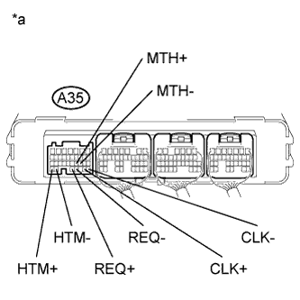
Text in Illustration *a Component without harness connected
(Power Management Control ECU)
Measure the resistance according to the value(s) in the table below.
Standard Resistance Tester Connection Switch Condition Specified Condition A35-34 (HTM+) - A35-33 (HTM-) Power switch off 80 to 170 Ω A35-21 (MTH+) - A35-20 (MTH-) Power switch off 80 to 170 Ω A35-32 (REQ+) - A35-31 (REQ-) Power switch off 80 to 170 Ω A35-29 (CLK+) - A35-28 (CLK-) Power switch off 80 to 170 Ω -
Reconnect the A35 power management control ECU connector.
NG
REPLACE POWER MANAGEMENT CONTROL ECU Click here
OK
-
-
CHECK CONNECTOR CONNECTION CONDITION (GENERATOR RESOLVER CONNECTOR)
-
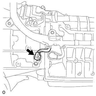
Remove the hybrid vehicle transmission assembly Click here.
-
Check the connection condition of the generator resolver connector and the contact pressure of each terminal. Check the terminals for deformation, and check the connector for water ingress and foreign matter Click here.
OK - The connector is connected securely. - The terminals are not deformed and are connected securely. - No water or foreign matter in the connector. Result Result Proceed to OK A NG (The connector is not connected securely.) B NG (The terminals are not making secure contact or are deformed, or water or foreign matter exists in the connector.) C
B
CONNECT SECURELY
C
REPAIR OR REPLACE HARNESS OR CONNECTOR
A
-
-
CHECK CONNECTOR CONNECTION CONDITION (MOTOR RESOLVER CONNECTOR)
-
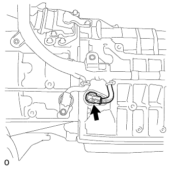
Check the connection condition of the motor resolver connector and the contact pressure of each terminal. Check the terminals for deformation, and check the connector for water ingress and foreign matter Click here.
OK - The connector is connected securely. - The terminals are not deformed and are connected securely. - No water or foreign matter in the connector. Result Result Proceed to OK A NG (The connector is not connected securely.) B NG (The terminals are not making secure contact or are deformed, or water or foreign matter exists in the connector.) C -
Install the hybrid vehicle transmission assembly.
B
CONNECT SECURELY
C
REPAIR OR REPLACE HARNESS OR CONNECTOR
A 
REPLACE INVERTER WITH CONVERTER ASSEMBLY Click here
-
-
CHECK CONNECTOR CONNECTION CONDITION (GENERATOR RESOLVER CONNECTOR)
-
Remove the hybrid vehicle transmission assembly Click here.
-
Check the connection condition of the generator resolver connector and the contact pressure of each terminal. Check the terminals for deformation, and check the connector for water ingress and foreign matter Click here.
OK - The connector is connected securely. - The terminals are not deformed and are connected securely. - No water or foreign matter in the connector. Result Result Proceed to OK A NG (The connector is not connected securely.) B NG (The terminals are not making secure contact or are deformed, or water or foreign matter exists in the connector.) C
B
CONNECT SECURELY
C
REPAIR OR REPLACE HARNESS OR CONNECTOR
A
-
-
CHECK HARNESS AND CONNECTOR (INVERTER WITH CONVERTER ASSEMBLY - GENERATOR RESOLVER)
CAUTION:
Be sure to wear insulated gloves.
-
Check that the service plug grip is not installed.
Note
After removing the service plug grip, do not turn the power switch on (READY), unless instructed by the repair manual because this may cause a malfunction.
-
Disconnect the A38*1 or A74*2 inverter with converter assembly connector.
-
*1: for LHD
-
*2: for RHD
-
-
Disconnect the F50 generator resolver connector.
-
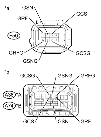
Text in Illustration *A for LHD *B for RHD *a Front view of wire harness connector
(to Generator Resolver)
*b Front view of wire harness connector
(to Inverter with Converter Assembly)
Measure the resistance according to the value(s) in the table below.
Standard Resistance (Check for Open) for LHD Tester Connection Switch Condition Specified Condition A38-20 (GRF) - F50-1 (GRF) Power switch off Below 1 Ω A38-9 (GRFG) - F50-5 (GRFG) Power switch off Below 1 Ω A38-18 (GSN) - F50-2 (GSN) Power switch off Below 1 Ω A38-7 (GSNG) - F50-6 (GSNG) Power switch off Below 1 Ω A38-17 (GCS) - F50-3 (GCS) Power switch off Below 1 Ω A38-6 (GCSG) - F50-7 (GCSG) Power switch off Below 1 Ω for RHD Tester Connection Switch Condition Specified Condition A74-20 (GRF) - F50-1 (GRF) Power switch off Below 1 Ω A74-9 (GRFG) - F50-5 (GRFG) Power switch off Below 1 Ω A74-18 (GSN) - F50-2 (GSN) Power switch off Below 1 Ω A74-7 (GSNG) - F50-6 (GSNG) Power switch off Below 1 Ω A74-17 (GCS) - F50-3 (GCS) Power switch off Below 1 Ω A74-6 (GCSG) - F50-7 (GCSG) Power switch off Below 1 Ω Standard Resistance (Check for Short) for LHD Tester Connection Switch Condition Specified Condition A38-20 (GRF) or F50-1 (GRF) - Body ground and other terminals Power switch off 1 MΩ or higher A38-9 (GRFG) or F50-5 (GRFG) - Body ground and other terminals Power switch off 1 MΩ or higher A38-18 (GSN) or F50-2 (GSN) - Body ground and other terminals Power switch off 1 MΩ or higher A38-7 (GSNG) or F50-6 (GSNG) - Body ground and other terminals Power switch off 1 MΩ or higher A38-17 (GCS) or F50-3 (GCS) - Body ground and other terminals Power switch off 1 MΩ or higher A38-6 (GCSG) or F50-7 (GCSG) - Body ground and other terminals Power switch off 1 MΩ or higher for RHD Tester Connection Switch Condition Specified Condition A74-20 (GRF) or F50-1 (GRF) - Body ground and other terminals Power switch off 1 MΩ or higher A74-9 (GRFG) or F50-5 (GRFG) - Body ground and other terminals Power switch off 1 MΩ or higher A74-18 (GSN) or F50-2 (GSN) - Body ground and other terminals Power switch off 1 MΩ or higher A74-7 (GSNG) or F50-6 (GSNG) - Body ground and other terminals Power switch off 1 MΩ or higher A74-17 (GCS) or F50-3 (GCS) - Body ground and other terminals Power switch off 1 MΩ or higher A74-6 (GCSG) or F50-7 (GCSG) - Body ground and other terminals Power switch off 1 MΩ or higher Tech Tips
The generator resolver is not available as a supply part. If it requires replacement, replace the hybrid vehicle transmission assembly.
-
Reconnect the F50 generator resolver connector.
-
Reconnect the A38*1 or A74*2 inverter with converter assembly connector.
-
*1: for LHD
-
*2: for RHD
-
NG
REPAIR OR REPLACE HARNESS OR CONNECTOR
OK
REPLACE HYBRID VEHICLE TRANSMISSION ASSEMBLY Click here
-
-
CHECK CONNECTOR CONNECTION CONDITION (MOTOR RESOLVER CONNECTOR)
-
Remove the hybrid vehicle transmission assembly Click here.
-
Check the connection condition of the motor resolver connector and the contact pressure of each terminal. Check the terminals for deformation, and check the connector for water ingress and foreign matter Click here.
OK - The connector is connected securely. - The terminals are not deformed and are connected securely. - No water or foreign matter in the connector. Result Result Proceed to OK A NG (The connector is not connected securely.) B NG (The terminals are not making secure contact or are deformed, or water or foreign matter exists in the connector.) C
B
CONNECT SECURELY
C
REPAIR OR REPLACE HARNESS OR CONNECTOR
A
-
-
CHECK HARNESS AND CONNECTOR (INVERTER WITH CONVERTER ASSEMBLY - MOTOR RESOLVER)
CAUTION:
Be sure to wear insulated gloves.
-
Check that the service plug grip is not installed.
Note
After removing the service plug grip, do not turn the power switch on (READY), unless instructed by the repair manual because this may cause a malfunction.
-
Disconnect the A38*1 or A74*2 inverter with converter assembly connector.
-
*1: for LHD
-
*2: for RHD
-
-
Disconnect the F51 motor resolver connector.
-
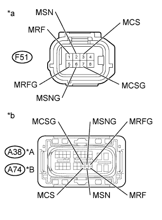
Text in Illustration *A for LHD *B for RHD *a Front view of wire harness connector
(to Motor Resolver)
*b Front view of wire harness connector
(to Inverter with Converter Assembly)
Measure the resistance according to the value(s) in the table below.
Standard Resistance (Check for Open) for LHD Tester Connection Switch Condition Specified Condition A38-40 (MRF) - F51-1 (MRF) Power switch off Below 1 Ω A38-29 (MRFG) - F51-5 (MRFG) Power switch off Below 1 Ω A38-39 (MSN) - F51-2 (MSN) Power switch off Below 1 Ω A38-28 (MSNG) - F51-6 (MSNG) Power switch off Below 1 Ω A38-38 (MCS) - F51-3 (MCS) Power switch off Below 1 Ω A38-27 (MCSG) - F51-7 (MCSG) Power switch off Below 1 Ω for RHD Tester Connection Switch Condition Specified Condition A74-40 (MRF) - F51-1 (MRF) Power switch off Below 1 Ω A74-29 (MRFG) - F51-5 (MRFG) Power switch off Below 1 Ω A74-39 (MSN) - F51-2 (MSN) Power switch off Below 1 Ω A74-28 (MSNG) - F51-6 (MSNG) Power switch off Below 1 Ω A74-38 (MCS) - F51-3 (MCS) Power switch off Below 1 Ω A74-27 (MCSG) - F51-7 (MCSG) Power switch off Below 1 Ω Standard Resistance (Check for Short) for LHD Tester Connection Switch Condition Specified Condition A38-40 (MRF) or F51-1 (MRF) - Body ground and other terminals Power switch off 1 MΩ or higher A38-29 (MRFG) or F51-5 (MRFG) - Body ground and other terminals Power switch off 1 MΩ or higher A38-39 (MSN) or F51-2 (MSN) - Body ground and other terminals Power switch off 1 MΩ or higher A38-28 (MSNG) or F51-6 (MSNG) - Body ground and other terminals Power switch off 1 MΩ or higher A38-38 (MCS) or F51-3 (MCS) - Body ground and other terminals Power switch off 1 MΩ or higher A38-27 (MCSG) or F51-7 (MCSG) - Body ground and other terminals Power switch off 1 MΩ or higher for RHD Tester Connection Switch Condition Specified Condition A74-40 (MRF) or F51-1 (MRF) - Body ground and other terminals Power switch off 1 MΩ or higher A74-29 (MRFG) or F51-5 (MRFG) - Body ground and other terminals Power switch off 1 MΩ or higher A74-39 (MSN) or F51-2 (MSN) - Body ground and other terminals Power switch off 1 MΩ or higher A74-28 (MSNG) or F51-6 (MSNG) - Body ground and other terminals Power switch off 1 MΩ or higher A74-38 (MCS) or F51-3 (MCS) - Body ground and other terminals Power switch off 1 MΩ or higher A74-27 (MCSG) or F51-7 (MCSG) - Body ground and other terminals Power switch off 1 MΩ or higher Tech Tips
The motor resolver is not available as a supply part. If it requires replacement, replace the hybrid vehicle transmission assembly.
-
Reconnect the F51 motor resolver connector.
-
Reconnect the A38*1 or A74*2 inverter with converter assembly connector.
-
*1: for LHD
-
*2: for RHD
-
NG
REPAIR OR REPLACE HARNESS OR CONNECTOR
OK
REPLACE HYBRID VEHICLE TRANSMISSION ASSEMBLY Click here
-
-
CHECK HARNESS AND CONNECTOR (INVERTER WITH CONVERTER ASSEMBLY - IGCT NO. 4 FUSE)
CAUTION:
Be sure to wear insulated gloves.
-
Check that the service plug grip is not installed.
Note
After removing the service plug grip, do not turn the power switch on (READY), unless instructed by the repair manual because this may cause a malfunction.
-
Disconnect the A38*1 or A74*2 inverter with converter assembly connector.
-
*1: for LHD
-
*2: for RHD
-
-
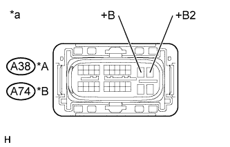
Text in Illustration *A for LHD *B for RHD *a Front view of wire harness connector
(to Inverter with Converter Assembly)
Measure the resistance according to the value(s) in the table below.
Standard Resistance for LHD Tester Connection Switch Condition Specified Condition A38-10 (+B) - Body ground Power switch off 10 kΩ or higher A38-11 (+B2) - Body ground Power switch off 10 kΩ or higher for RHD Tester Connection Switch Condition Specified Condition A74-10 (+B) - Body ground Power switch off 10 kΩ or higher A74-11 (+B2) - Body ground Power switch off 10 kΩ or higher -
Reconnect the A38*1 or A74*2 inverter with converter assembly connector.
-
*1: for LHD
-
*2: for RHD
-
NG
REPAIR OR REPLACE HARNESS OR CONNECTOR Click here
OK
-
-
REPLACE INVERTER WITH CONVERTER ASSEMBLY
NEXT
REPLACE FUSE (IGCT NO. 4)
-
REPAIR OR REPLACE HARNESS OR CONNECTOR
NEXT
REPLACE FUSE (IGCT NO. 4)
-
CHECK HYBRID VEHICLE TRANSMISSION ASSEMBLY (GENERATOR CABLE CONNECTION CONDITION)
CAUTION:
Be sure to wear insulated gloves.
-
Check that the service plug grip is not installed.
Note
After removing the service plug grip, do not turn the power switch on (READY), unless instructed by the repair manual because this may cause a malfunction.
-
Remove the hybrid vehicle transmission assembly Click here.
-
Check that the bolts for the generator cable are tightened to the specified torque, the generator cable is connected securely, and there are no contact problems.
Specified Condition T=8.0 N*m (82 kgf*cm, 71 in.*lbf) Note
Make sure that the tightening torque of the bolt is between 6.4 and 9.6 N*m (65 and 98 kgf*cm, 57 and 85 in.*lbf).
-
Disconnect the generator cable from the hybrid vehicle transmission assembly.
-
Check for arc marks at the terminals for the generator cable.
Result Result Proceed to The terminals are connected securely and there are no contact problems. There are no arc marks. A The terminals are not connected securely and there is a contact problem. There are arc marks. B The terminals are not connected securely and there is a contact problem. There are no arc marks. C The terminals are connected securely and there are no contact problems. There are arc marks. B -
Connect the generator cable to the hybrid vehicle transmission assembly.
-
Install the hybrid vehicle transmission assembly.
B
REPLACE MALFUNCTIONING PARTS
C
CONNECT SECURELY
A
-
-
CHECK GENERATOR CABLE
CAUTION:
Be sure to wear insulated gloves.
-
Check that the service plug grip is not installed.
Note
After removing the service plug grip, do not turn the power switch on (READY), unless instructed by the repair manual because this may cause a malfunction.
-
Remove the generator cable Click here.
-
Using a megohmmeter set to 500 V, measure the resistance according to the value(s) in the table below.
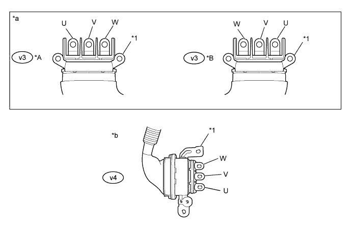
Text in Illustration *A for LHD *B for RHD *1 Shield ground - - *a Generator Cable
(Inverter with Converter Assembly Side)
*b Generator Cable
(Hybrid Vehicle Transmission Assembly Side)
Note
Be sure to set the megohmmeter to 500 V when performing this test. Using a setting higher than 500 V can result in damage to the component being inspected.
Standard Resistance for LHD Tester Connection Switch Condition Specified Condition v3-3 (W) - Body ground and shield ground Power switch off 100 MΩ or higher v3-2 (V) - Body ground and shield ground Power switch off 100 MΩ or higher v3-1 (U) - Body ground and shield ground Power switch off 100 MΩ or higher for RHD Tester Connection Switch Condition Specified Condition v3-1 (W) - Body ground and shield ground Power switch off 100 MΩ or higher v3-2 (V) - Body ground and shield ground Power switch off 100 MΩ or higher v3-3 (U) - Body ground and shield ground Power switch off 100 MΩ or higher Note
Wrap the terminal of the generator cable with insulating tape to prevent them from coming into contact with body ground.
-
Measure the resistance according to the value(s) in the table below.
Standard Resistance for LHD Tester Connection Switch Condition Specified Condition v3-3 (W) - v4-3 (U) Power switch off 100 MΩ or higher v3-2 (V) - v4-1 (W) Power switch off 100 MΩ or higher v3-1 (U) - v4-2 (V) Power switch off 100 MΩ or higher v3-3 (W) - v4-1 (W) Power switch off Below 1 Ω v3-2 (V) - v4-2 (V) Power switch off Below 1 Ω v3-1 (U) - v4-3 (U) Power switch off Below 1 Ω for RHD Tester Connection Switch Condition Specified Condition v3-1 (W) - v4-3 (U) Power switch off 100 MΩ or higher v3-2 (V) - v4-1 (W) Power switch off 100 MΩ or higher v3-3 (U) - v4-2 (V) Power switch off 100 MΩ or higher v3-1 (W) - v4-1 (W) Power switch off Below 1 Ω v3-2 (V) - v4-2 (V) Power switch off Below 1 Ω v3-3 (U) - v4-3 (U) Power switch off Below 1 Ω -
Install the generator cable.
NG
REPLACE GENERATOR CABLE Click here
OK
REPLACE HYBRID VEHICLE TRANSMISSION ASSEMBLY Click here
-
-
CHECK HYBRID VEHICLE TRANSMISSION ASSEMBLY (MOTOR CABLE CONNECTION CONDITION)
CAUTION:
Be sure to wear insulated gloves.
-
Check that the service plug grip is not installed.
Note
After removing the service plug grip, do not turn the power switch on (READY), unless instructed by the repair manual because this may cause a malfunction.
-
Remove the hybrid vehicle transmission assembly Click here.
-
Check that the bolts for the motor cable are tightened to the specified torque, the motor cable is connected securely, and there are no contact problems.
Specified Condition T=8.0 N*m (82 kgf*cm, 71 in.*lbf) Note
Make sure that the tightening torque of the bolt is between 6.4 and 9.6 N*m (65 and 98 kgf*cm, 57 and 85 in.*lbf).
-
Disconnect the motor cable from the hybrid vehicle transmission assembly.
-
Check for arc marks at the terminals for the motor cable.
Result Result Proceed to The terminals are connected securely and there are no contact problems. There are no arc marks. A The terminals are not connected securely and there is a contact problem. There are arc marks. B The terminals are not connected securely and there is a contact problem. There are no arc marks. C The terminals are connected securely and there are no contact problems. There are arc marks. B -
Connect the motor cable to the hybrid vehicle transmission assembly.
-
Install the hybrid vehicle transmission assembly.
B
REPLACE MALFUNCTIONING PARTS
C
CONNECT SECURELY
A
-
-
CHECK MOTOR CABLE
CAUTION:
Be sure to wear insulated gloves.
-
Check that the service plug grip is not installed.
Note
After removing the service plug grip, do not turn the power switch on (READY), unless instructed by the repair manual because this may cause a malfunction.
-
Remove the motor cable Click here.
-
Using a megohmmeter set to 500 V, measure the resistance according to the value(s) in the table below.
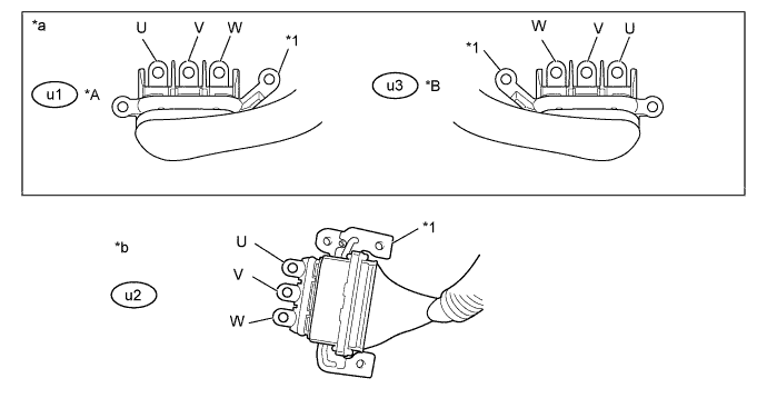
Text in Illustration *A for LHD *B for RHD *1 Shield ground - - *a Motor Cable
(Inverter with Converter Assembly Side)
*b Motor Cable
(Hybrid Vehicle Transmission Assembly Side)
Note
Be sure to set the megohmmeter to 500 V when performing this test. Using a setting higher than 500 V can result in damage to the component being inspected.
Standard Resistance for LHD Tester Connection Switch Condition Specified Condition u1-3 (W) - Body ground and shield ground Power switch off 100 MΩ or higher u1-2 (V) - Body ground and shield ground Power switch off 100 MΩ or higher u1-1 (U) - Body ground and shield ground Power switch off 100 MΩ or higher for RHD Tester Connection Switch Condition Specified Condition u3-1 (W) - Body ground and shield ground Power switch off 100 MΩ or higher u3-2 (V) - Body ground and shield ground Power switch off 100 MΩ or higher u3-3 (U) - Body ground and shield ground Power switch off 100 MΩ or higher Note
Wrap the terminal of the motor cable with insulating tape to prevent them from coming into contact with body ground.
-
Measure the resistance according to the value(s) in the table below.
Standard Resistance for LHD Tester Connection Switch Condition Specified Condition u1-3 (W) - u2-1 (U) Power switch off 100 MΩ or higher u1-2 (V) - u2-3 (W) Power switch off 100 MΩ or higher u1-1 (U) - u2-2 (V) Power switch off 100 MΩ or higher u1-3 (W) - u2-3 (W) Power switch off Below 1 Ω u1-2 (V) - u2-2 (V) Power switch off Below 1 Ω u1-1 (U) - u2-1 (U) Power switch off Below 1 Ω for RHD Tester Connection Switch Condition Specified Condition u3-1 (W) - u2-1 (U) Power switch off 100 MΩ or higher u3-2 (V) - u2-3 (W) Power switch off 100 MΩ or higher u3-3 (U) - u2-2 (V) Power switch off 100 MΩ or higher u3-1 (W) - u2-3 (W) Power switch off Below 1 Ω u3-2 (V) - u2-2 (V) Power switch off Below 1 Ω u3-3 (U) - u2-1 (U) Power switch off Below 1 Ω -
Install the motor cable.
NG
REPLACE MOTOR CABLE Click here
OK
REPLACE HYBRID VEHICLE TRANSMISSION ASSEMBLY Click here
-
-
REPLACE HV COOLANT
-
Замените охлаждающую жидкость гибридной системы охлаждающей жидкостью с концентрацией (температурой замерзания), соответствующей условиям эксплуатации автомобиля (см. стр. Click here).
NEXT
COMPLETED
-