AIRBAG SYSTEM SRS Warning Light Remains ON
DESCRIPTION
The SRS warning light is located on the combination meter assembly.
When the SRS is normal, the SRS warning light comes on for approximately 6 seconds after the ignition switch is turned from off to ON, and then goes off automatically.
If there is a malfunction in the SRS, the SRS warning light comes on to inform the driver of a problem.
The SRS is equipped with a voltage-increase circuit (DC-DC converter) in the airbag ECU assembly in case the source voltage drops.
When the battery voltage drops, the voltage-increase circuit (DC-DC converter) functions to increase the voltage of the SRS to normal voltage. In addition, when the voltage drops, the SRS warning light will illuminate.
A malfunction in this circuit is not stored in the airbag ECU assembly. The SRS warning light automatically goes off when the source voltage returns to normal.
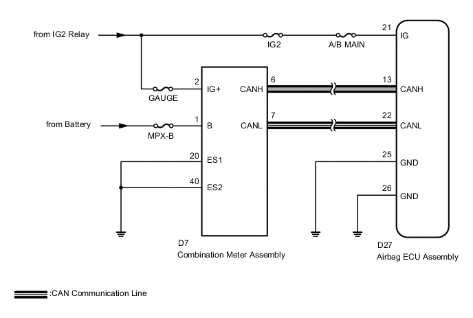
The signal to illuminate the SRS warning light is transmitted from the airbag ECU assembly to the combination meter assembly through the CAN communication system.
WIRING DIAGRAM
CAUTION / NOTICE / HINT
Note
-
After turning the ignition switch off, waiting time may be required before disconnecting the cable from the negative (-) battery terminal. Therefore, make sure to read the disconnecting the cable from the negative (-) battery terminal notices before proceeding with work Click here.
-
Inspect the fuses for circuits related to this system before performing the following inspection procedure.
PROCEDURE
-
CHECK SRS WARNING LIGHT OPERATION
-
Check the SRS warning light operation approximately 6 seconds after the ignition switch is turned to ON.
Result SRS Warning Light Illumination Proceed to Remains on A Goes off and then comes on again B
B 
CHECK CAN COMMUNICATION SYSTEM Click here
A 
-
-
CHECK BATTERY VOLTAGE
-
Measure the voltage of the battery.
Standard Voltage 11 to 14 V
NG 
INSPECT CHARGING SYSTEM AND BATTERY Click here
OK
-
-
CHECK CONNECTOR
-
Turn the ignition switch off.
-
Disconnect the cable from the negative (-) battery terminal.
CAUTION:
Wait at least 90 seconds after disconnecting the cable from the negative (-) battery terminal to disable the SRS system.
-
Check that the connector is properly connected to the airbag ECU assembly.
OK The connector is properly connected. Tech Tips
If the connector is not connected securely, reconnect the connector and proceed to the next inspection.
-
Disconnect the connector from the airbag ECU assembly.
-
Check that the terminal of the connector is not damaged.
OK The terminal is not deformed or damaged.
NG
REPLACE WIRE HARNESS
OK
-
-
CHECK WIRE HARNESS (AIRBAG ECU ASSEMBLY - BODY GROUND)
-
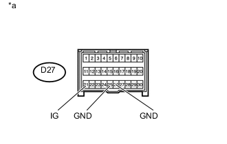
Text in Illustration *a Front view of wire harness connector
(to Airbag ECU Assembly)
Connect the cable to the negative (-) battery terminal.
-
Turn the ignition switch to ON.
-
Operate all components of the electrical system (defogger, wipers, headlights, heater blower, etc.).
-
Measure the voltage according to the value(s) in the table below.
Standard Voltage Tester Connection Condition Specified Condition D27-21 (IG) - Body ground Ignition switch ON 8 to 16 V -
Turn the ignition switch off.
-
Measure the resistance according to the value(s) in the table below.
Standard Resistance Tester Connection Condition Specified Condition D27-25 (GND) - Body ground Always Below 1 Ω D27-26 (GND) - Body ground Always Below 1 Ω
NG
REPLACE WIRE HARNESS
OK
-
-
CHECK SRS WARNING LIGHT
-
Turn the ignition switch to ON.
-
Check the SRS warning light condition.
OK After the primary check period, the SRS warning light goes off for approximately 10 seconds and turns back on. Tech Tips
The primary check period is approximately 6 seconds after the ignition switch is turned to ON.
OK
REPLACE AIRBAG ECU ASSEMBLY Click here
NG
REPLACE COMBINATION METER ASSEMBLY Click here
-
-
CHECK CAN COMMUNICATION SYSTEM
-
Use the GTS to check if the CAN communication system is functioning normally.
Tech Tips
-
Refer to Bus Check for the CAN communication system Click here.
-
The airbag ECU assembly is connected to the CAN communication system. Therefore, before starting troubleshooting, make sure to check that there is no trouble in the CAN communication system.
Result Result Proceed to DTC is not output A DTC is output B -
B
GO TO CAN COMMUNICATION SYSTEM Click here
A
-
-
CHECK BATTERY VOLTAGE
-
Measure the voltage of the battery.
Standard Voltage 11 to 14 V
NG
INSPECT CHARGING SYSTEM AND BATTERY Click here
OK
-
-
CHECK CONNECTOR
-
Turn the ignition switch off.
-
Disconnect the cable from the negative (-) battery terminal.
CAUTION:
Wait at least 90 seconds after disconnecting the cable from the negative (-) battery terminal to disable the SRS system.
-
Check that the connector is properly connected to the airbag ECU assembly.
OK The connector is properly connected. Tech Tips
If the connector is not connected securely, reconnect the connector and proceed to the next inspection.
-
Disconnect the connector from the airbag ECU assembly.
-
Check that the terminal of the connector is not damaged.
OK The terminal is not deformed or damaged.
NG
REPLACE WIRE HARNESS
OK
-
-
CHECK WIRE HARNESS (AIRBAG ECU ASSEMBLY - BODY GROUND)
-
Text in Illustration *a Front view of wire harness connector
(to Airbag ECU Assembly)
Connect the cable to the negative (-) battery terminal.
-
Turn the ignition switch to ON.
-
Operate all components of the electrical system (defogger, wipers, headlights, heater blower, etc.).
-
Measure the voltage according to the value(s) in the table below.
Standard Voltage Tester Connection Condition Specified Condition D27-21 (IG) - Body ground Ignition switch ON 8 to 16 V -
Turn the ignition switch off.
-
Measure the resistance according to the value(s) in the table below.
Standard Resistance Tester Connection Condition Specified Condition D27-25 (GND) - Body ground Always Below 1 Ω D27-26 (GND) - Body ground Always Below 1 Ω
NG
REPLACE WIRE HARNESS
OK
-
-
CHECK CONNECTOR
-
Disconnect the cable from the negative (-) battery terminal.
CAUTION:
Wait at least 90 seconds after disconnecting the cable from the negative (-) battery terminal to disable the SRS system.
-
Check that the connector is properly connected to the combination meter assembly.
OK The connector is properly connected. Tech Tips
If the connector is not connected securely, reconnect the connector and proceed to the next inspection.
-
Disconnect the connector from the combination meter assembly.
-
Check that the terminal of the connector is not damaged.
OK The terminal is not deformed or damaged.
NG
REPAIR OR REPLACE CONNECTOR
OK
-
-
CHECK WIRE HARNESS (COMBINATION METER ASSEMBLY - BODY GROUND)
-
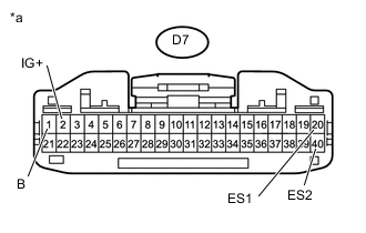
Text in Illustration *a Front view of wire harness connector
(to Combination Meter Assembly)
Connect the cable to the negative (-) battery terminal.
-
Turn the ignition switch to ON.
-
Measure the voltage according to the value(s) in the table below.
Standard Voltage Tester Connection Condition Specified Condition D7-1 (B) - Body ground Always 11 to 14 V D7-2 (IG+) - Body ground Ignition switch ON 11 to 14 V -
Turn the ignition switch off.
-
Measure the resistance according to the value(s) in the table below.
Standard Resistance Tester Connection Condition Specified Condition D7-20 (ES1) - Body ground Always Below 1 Ω D7-40 (ES2) - Body ground Always Below 1 Ω
NG
REPAIR OR REPLACE WIRE HARNESS
OK
-
-
CHECK SRS WARNING LIGHT
-
Disconnect the cable from the negative (-) battery terminal.
CAUTION:
Wait at least 90 seconds after disconnecting the cable from the negative (-) battery terminal to disable the SRS system.
-
Connect the connector to the combination meter assembly.
-
Connect the cable to the negative (-) battery terminal.
-
Turn the ignition switch to ON.
-
Check the SRS warning light condition.
OK After the primary check period, the SRS warning light goes off for approximately 10 seconds and turns back on. Tech Tips
The primary check period is approximately 6 seconds after the ignition switch is turned to ON.
OK
REPLACE AIRBAG ECU ASSEMBLY Click here
NG
REPLACE COMBINATION METER ASSEMBLY Click here
-