VEHICLE STABILITY CONTROL SYSTEM, Diagnostic DTC:C1494, C1495
| DTC Code | DTC Name |
|---|---|
| C1494 | Reverse Switch OFF Stuck |
| C1495 | Reverse Switch ON Stuck |
DESCRIPTION
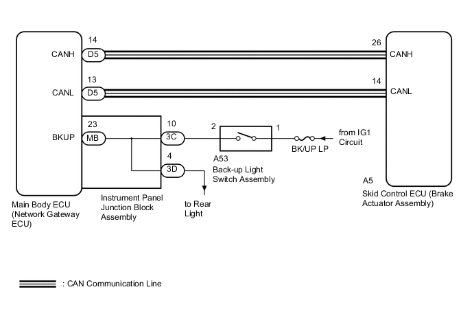
The skid control ECU (brake actuator assembly) receives signals from the back-up light switch assembly via CAN communication.
If any faults are present in the CAN communication cable with the main body ECU (network gateway ECU), DTC U0140 (Lost Communication with Main body ECU ) is stored.
| DTC No. | DTC Detection Condition | Trouble Area |
|---|---|---|
| C1494 | Back-up switch system circuit has a malfunction |
|
| C1495 | Back-up switch system circuit has a malfunction |
|
WIRING DIAGRAM
CAUTION / NOTICE / HINT
Note
-
When replacing the skid control ECU (brake actuator assembly), perform VSC sensor neutral memorization Click here.
-
Inspect the fuses for circuits related to this system before performing the following inspection procedure.
PROCEDURE
-
CHECK CAN COMMUNICATION SYSTEM
-
Check if a CAN communication system DTC is output Click here.
Result Result Proceed to DTC is not output. A DTC is output. B
B 
GO TO CAN COMMUNICATION SYSTEM (HOW TO PROCEED WITH TROUBLESHOOTING) Click here
A 
-
-
READ VALUE USING GTS (MT REVERSE SW)
-
Connect the GTS to the DLC3.
-
Turn the ignition switch to ON.
-
Select the Data List using the GTS.
Body Electrical / Main Body / Data List Tester Display Measurement Item/Range Normal Condition Diagnostic Note MT Reverse SW Back-up light switch assembly status / ON or OFF ON: Shift lever in R
OFF: Shift lever not in R
- OK OK: The GTS displays on or off according to shift lever operation.
NG 
INSPECT BACK-UP LIGHT SWITCH ASSEMBLY Click here
OK
-
-
RECONFIRM DTC OUTPUT
-
Clear the DTCs Click here.
-
Turn the ignition switch off.
-
Start the engine.
-
Drive the vehicle at a speed of 45 km/h (28 mph) or more for at least 120 seconds.
-
Check if the same DTC is output Click here.
Result Result Proceed to DTCs C1494 and/or C1495 are not output. A DTCs C1494 and/or C1495 are output. B
B
REPLACE BRAKE ACTUATOR ASSEMBLY Click here
A
-
-
CHECK OPERATION
-
Check the operation of the rear light.
OK The rear light operates normally.
OK
REPLACE MAIN BODY ECU (NETWORK GATEWAY ECU) Click here
GO TO REAR LIGHT ASSEMBLY
-
-
INSPECT BACK-UP LIGHT SWITCH ASSEMBLY
-
Inspect the back-up light switch assembly Click here.
NG
REPLACE BACK-UP LIGHT SWITCH ASSEMBLY Click here
OK
-
-
CHECK HARNESS AND CONNECTOR (BACK-UP LIGHT SWITCH ASSEMBLY POWER SOURCE TERMINAL)
-
Disconnect the back-up light switch assembly connector.
-
Measure the voltage according to the value(s) in the table below.
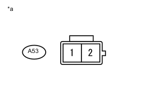
Standard Voltage Tester Connection Switch Condition Specified Condition A53-1 - Body ground Ignition Switch ON 11 to 14 V Text in Illustration *a Front view of wire harness connector
(to Back-Up Light Switch Assembly)
NG
REPAIR OR REPLACE HARNESS AND CONNECTOR
OK
-
-
CHECK HARNESS AND CONNECTOR (INSTRUMENT PANEL JUNCTION BLOCK - BACK-UP LIGHT SWITCH)
-
Disconnect the instrument panel junction block assembly connector.
-
Disconnect the back-up light switch assembly connector.
-
Measure the resistance according to the value(s) in the table below.
Standard resistance Tester Connection Condition Specified Condition 3C-10 - A53-2 Always Below 1 Ω
NG
REPAIR OR REPLACE HARNESS AND CONNECTOR
OK
-
-
INSPECT INSTRUMENT PANEL JUNCTION BLOCK ASSEMBLY
-
Remove the instrument panel junction block assembly Click here.
-
Remove the main body ECU (network gateway ECU) from the instrument panel junction block assembly Click here.
-
Measure the resistance according to the value(s) in the table below.
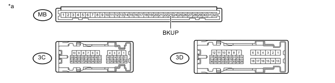
Text in Illustration *a Component without harness connected
(Instrument Panel Junction Block Assembly)
- - Standard resistance Tester Connection Condition Specified Condition MB-23 (BKUP) - 3C-10 Always Below 1 Ω MB-23 (BKUP) - 3D-4 Always Below 1 Ω 3C-10 - 3D-4 Always Below 1 Ω MB-23 (BKUP) - Body ground Always 10 kΩ or higher
OK
REPLACE MAIN BODY ECU (NETWORK GATEWAY ECU) Click here
NG
REPLACE INSTRUMENT PANEL JUNCTION BLOCK ASSEMBLY Click here
-