VEHICLE STABILITY CONTROL SYSTEM Hill Start Assist Indicator Circuit
DESCRIPTION
The skid control ECU (brake actuator assembly) controls display of the hill start assist indicator in the combination meter assembly via CAN communication.
Turning the hill-start assist control on and off, the hill start assist indicator in the combination meter assembly turns on and off. If the hill-start assist control is not functioning properly when the system is turned on, the hill start assist indicator goes off and the buzzer sounds.
WIRING DIAGRAM
Refer to TRC OFF Indicator Light Remains ON Click here.
CAUTION / NOTICE / HINT
Note
-
When replacing the skid control ECU (brake actuator assembly), perform VSC sensor neutral memorization Click here.
-
Inspect the fuses for circuits related to this system before performing the following inspection procedure.
PROCEDURE
-
PRE-CHECK
-
Check the status of the hill start assist indicator when the hill-start assist control is not functioning.
OK The hill start assist indicator is on. Tech Tips
When the hill start assist indicator is off or the buzzer sounds, the ECM enters fail-safe mode, and the hill-start assist control does not function.
-
Check that the hill-start assist control was not deactivated by operation of the VSC OFF switch.
Result The hill-start assist control was deactivated.
B 
HILL-START ASSIST FUNCTION ON
A 
-
-
CHECK IF BRAKE ACTUATOR ASSEMBLY CONNECTOR IS SECURELY CONNECTED
-
Move the connector and wire harness of the skid control ECU (brake actuator assembly) lightly up and down and to right and left to check the status of the hill start assist indicator in the combination meter assembly.
OK The status of the hill start assist indicator does not change.
NG
REPAIR OR REPLACE HARNESS OR CONNECTOR
OK
-
-
CHECK CAN COMMUNICATION SYSTEM
-
Check if a CAN communication system DTC is output Click here.
OK No DTC is output.
NG
GO TO CAN COMMUNICATION SYSTEM (HOW TO PROCEED WITH TROUBLESHOOTING)
OK
-
-
READ VALUE USING GTS (HILL START ASSIST INDICATOR AND HA-CTRL BUZZER)
-
Connect the GTS to the DLC3.
-
Turn the ignition switch to ON.
-
Select the Active Test using the GTS Click here.
ABS/VSC/TRC Tester Display Test Part Control Range Diagnostic Note Hill Start Assist Indicator Hill Start Assist Indicator Indicator light ON/OFF Observe combination meter assembly HA-CTRL Buzzer HA-CTRL buzzer Buzzer ON/OFF Buzzer can be heard
Tech Tips
If the hill-start assist function is set to OFF, the buzzer will not sound even when HA-CTRL buzzer ON/OFF operation is performed.
-
Perform Active Test for the hill start assist indicator and the HA-CTRL buzzer.
OK The hill start assist indicator and the HA-CTRL buzzer are turned on and off when Active Test ON/OFF is performed.
NG
GO TO METER / GAUGE / DISPLAY (HOW TO PROCEED WITH TROUBLESHOOTING)
OK
-
-
INSPECT VSC OFF SWITCH
-
Remove the VSC OFF switch Click here.
-
Inspect the VSC OFF switch Click here.
NG
REPLACE VSC OFF SWITCH Click here
OK
-
-
CHECK HARNESS AND CONNECTOR (BRAKE ACTUATOR ASSEMBLY - VSC OFF SWITCH)
-
Turn the ignition switch off.
-
Disconnect the VSC OFF switch connector.
-
Disconnect the skid control ECU (brake actuator assembly) connector.
-
Measure the resistance according to the value(s) in the table below.
Standard Resistance Tester Connection Condition Specified Condition D35-5 - A5-12 (CSW1) Always Below 1 Ω A5-12 (CSW1) - Body ground Always 10 kΩ or higher D35-8 - Body ground Always Below 1 Ω
NG
REPAIR OR REPLACE HARNESS OR CONNECTOR
OK
-
-
CHECK HARNESS AND CONNECTOR (+BS, IG1, GND1 TERMINAL)
-
Make sure that there is no looseness at the locking part and the connecting part of the connector.
OK No malfunction is detected. -
Turn the ignition switch off.
-
Disconnect the skid control ECU (brake actuator assembly) connector.
-
Check that there is no deformation or corrosion on the case or the terminals of the connector.
OK No deformation or corrosion is present. -
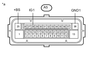
Text in Illustration *a Front view of wire harness connector
(to Skid Control ECU (Brake Actuator Assembly))
Measure the voltage according to the value(s) in the table below.
Standard Voltage Tester Connection Condition Specified Condition A5-25 (+BS) - Body ground Always 11 to 14 V A5-25 (+BS) - A5-38 (GND1) Always 11 to 14 V A5-28 (IG1) - Body ground Ignition Switch ON 11 to 14 V A5-28 (IG1) - A5-38 (GND1) Ignition Switch ON 11 to 14 V
OK
REPLACE BRAKE ACTUATOR ASSEMBLY Click here
NG
REPAIR OR REPLACE HARNESS OR CONNECTOR
-