REAR SUSPENSION MEMBER INSTALLATION
PROCEDURE
-
INSTALL REAR NO. 1 DIFFERENTIAL MOUNT CUSHION
-
INSTALL REAR NO. 2 DIFFERENTIAL MOUNT CUSHION
-
TEMPORARILY INSTALL REAR UPPER CONTROL ARM ASSEMBLY LH
-
TEMPORARILY INSTALL REAR UPPER CONTROL ARM ASSEMBLY RH
Tech Tips
Use the same procedure described for the LH side.
-
INSTALL REAR SUSPENSION MEMBER SUB-ASSEMBLY
-
Support the rear suspension member sub-assembly with an engine lifter using 4 attachments or equivalent tools.
Note
-
Make sure to secure the rear suspension member sub-assembly to prevent it from dropping.
-
Use the attachments to keep the rear suspension member sub-assembly level.
-
-
Raise the rear suspension member sub-assembly until there is no clearance between the rear suspension member sub-assembly and the vehicle body.
Note
When raising the rear suspension member sub-assembly, be careful not to damage the vehicle body or other components installed on the vehicle.
-
While supporting the rear suspension member sub-assembly with a high transmission jack, using the 4 bolts B and 4 new bolts A, install the suspension member sub-assembly, front support rear LH, front support rear RH, rear support upper and rear support lower all together.
Note
After temporarily tightening the bolts A in the order shown in the illustration, tighten them securely.
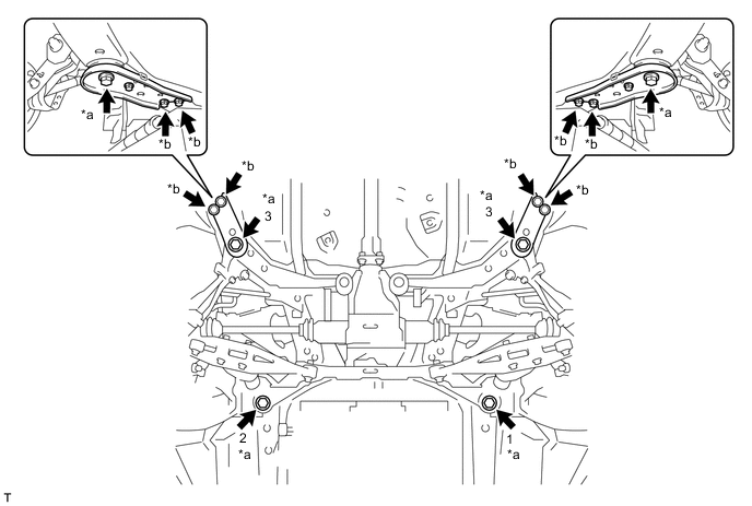
Text in Illustration *a Bolt A (New bolt) *b Bolt B - Torque:
- 145 N*m { 1479 kgf*cm, 107 ft.*lbf }
- (Bolt A)
- 70 N*m { 714 kgf*cm, 52 ft.*lbf }
- (Bolt B)
-
-
TEMPORARILY INSTALL TOE CONTROL LINK SUB-ASSEMBLY LH
-
Install the toe control link sub-assembly LH and insert the toe adjust cam from the front of the vehicle. Then, install the No. 2 toe adjust plate and temporarily install a new nut.
Note
Align the matchmarks on the rear suspension member and rear No. 2 suspension toe adjust plate.
-
-
TEMPORARILY INSTALL TOE CONTROL LINK SUB-ASSEMBLY RH
Tech Tips
Use the same procedure described for the LH side.
-
TEMPORARILY INSTALL REAR NO. 2 SUSPENSION ARM ASSEMBLY LH
-
Temporarily install the rear No. 2 suspension arm assembly LH to the rear suspension member with the bolt and a new nut.
Note
Insert the bolt from inside the vehicle.
-
-
TEMPORARILY INSTALL REAR NO. 2 SUSPENSION ARM ASSEMBLY RH
Tech Tips
Use the same procedure described for the LH side.
-
TEMPORARILY INSTALL REAR SHOCK ABSORBER WITH COIL SPRING LH
-
Temporarily install the rear shock absorber assembly to the rear No. 2 suspension arm with the bolt and a new nut.
Tech Tips
The bolt may be inserted from either direction.
-
-
TEMPORARILY INSTALL REAR SHOCK ABSORBER WITH COIL SPRING RH
Tech Tips
Use the same procedure described for the LH side.
-
TEMPORARILY INSTALL REAR NO. 1 SUSPENSION ARM ASSEMBLY LH
-
Temporarily install the rear No. 1 suspension arm assembly LH to the rear suspension member with the new bolt and new nut.
Note
Insert the bolt from outside the vehicle.
-
-
TEMPORARILY INSTALL REAR NO. 1 SUSPENSION ARM ASSEMBLY RH
Tech Tips
Use the same procedure described for the LH side.
-
INSTALL REAR STABILIZER BAR
-
TEMPORARILY TIGHTEN STABILIZER LINK SUB-ASSEMBLY (for LH Side)
-
TEMPORARILY TIGHTEN STABILIZER LINK SUB-ASSEMBLY (for RH Side)
Tech Tips
Use the same procedure described for the LH side.
-
INSTALL PARKING BRAKE CABLE SUPPORT BRACKET (for LH Side)
-
Install the parking brake cable support bracket with the bolt.
- Torque:
- 18 N*m { 184 kgf*cm, 13 ft.*lbf }
-
-
INSTALL PARKING BRAKE CABLE SUPPORT BRACKET (for RH Side)
Tech Tips
Use the same procedure described for the LH side.
-
INSTALL NO. 2 FUEL TANK PROTECTOR (for Clamp Type)
-
INSTALL NO. 1 FUEL TANK PROTECTOR (for Clamp Type)
-
INSTALL NO. 3 FUEL TANK PROTECTOR (for Metal Type)
-
INSTALL NO. 3 PARKING BRAKE CABLE ASSEMBLY
-
Install the No. 3 parking brake cable assembly to the axle carrier with the clamp.
-
Install the No. 3 parking brake cable assembly to the rear suspension member lower stopper LH with the bolt.
- Torque:
- 18 N*m { 184 kgf*cm, 13 ft.*lbf }
-
-
INSTALL NO. 2 PARKING BRAKE CABLE ASSEMBLY
Tech Tips
Use the same procedure described for the LH side.
-
INSTALL REAR AXLE CARRIER SUB-ASSEMBLY LH
-
INSTALL REAR AXLE CARRIER SUB-ASSEMBLY RH
Tech Tips
Use the same procedure described for the LH side.
-
INSTALL REAR DRIVE SHAFT ASSEMBLY LH
-
INSTALL REAR DRIVE SHAFT ASSEMBLY RH
Tech Tips
Use the same procedure described for the LH side.
-
INSTALL REAR DIFFERENTIAL CARRIER ASSEMBLY
-
INSTALL PROPELLER WITH CENTER BEARING SHAFT ASSEMBLY
-
INSTALL EXHAUST TAIL PIPE ASSEMBLY
-
INSTALL REAR HEIGHT CONTROL SENSOR SUB-ASSEMBLY LH (w/ HID Headlight System)
-
STABILIZE SUSPENSION
-
FULLY TIGHTEN REAR UPPER CONTROL ARM ASSEMBLY LH
-
FULLY TIGHTEN REAR UPPER CONTROL ARM ASSEMBLY RH
Tech Tips
Use the same procedure described for the LH side.
-
FULLY TIGHTEN TOE CONTROL LINK SUB-ASSEMBLY LH
-
FULLY TIGHTEN TOE CONTROL LINK SUB-ASSEMBLY RH
Tech Tips
Use the same procedure described for the LH side.
-
TEMPORARILY INSTALL REAR NO. 2 SUSPENSION ARM ASSEMBLY LH
-
Fully tighten the nut holding the rear shock absorber.
- Torque:
- 80 N*m { 816 kgf*cm, 59 ft.*lbf }
-
Fully tighten the nut on the rear suspension member sub-assembly side.
- Torque:
- 80 N*m { 816 kgf*cm, 59 ft.*lbf }
-
-
TEMPORARILY INSTALL REAR NO. 2 SUSPENSION ARM ASSEMBLY RH
Tech Tips
Use the same procedure described for the LH side.
-
FULLY TIGHTEN STABILIZER LINK SUB-ASSEMBLY (for LH Side)
-
FULLY TIGHTEN STABILIZER LINK SUB-ASSEMBLY (for RH Side)
Tech Tips
Use the same procedure described for the LH side.
-
FULLY TIGHTEN REAR NO. 1 SUSPENSION ARM ASSEMBLY LH
-
Fully tighten the bolt on the rear suspension member side of the rear No. 1 suspension arm assembly LH.
- Torque:
- 110 N*m { 1122 kgf*cm, 81 ft.*lbf }
-
-
FULLY TIGHTEN REAR NO. 1 SUSPENSION ARM ASSEMBLY RH
Tech Tips
Use the same procedure described for the LH side.
-
INSTALL REAR WHEELS
- Torque:
- 120 N*m { 1224 kgf*cm, 89 ft.*lbf }
-
INSPECT AND ADJUST REAR WHEEL ALIGNMENT
-
VSC SENSOR NEUTRAL MEMORIZATION
-
CHECK FOR SPEED SENSOR SIGNAL
-
HEIGHT CONTROL SENSOR SIGNAL INITIALIZE (w/ HID Headlight System)
-
ADJUST HEADLIGHT AIMING (w/ HID Headlight System)