AUTOMATIC TRANSMISSION SYSTEM, Diagnostic DTC:P0712, P0713

| DTC Code | DTC Name |
|---|---|
| P0712 | Transmission Fluid Temperature Sensor "A" Circuit Low Input |
| P0713 | Transmission Fluid Temperature Sensor "A" Circuit High Input |
DESCRIPTION
The oil temperature sensor within the valve body detects the oil temperature within the transmission hydraulic control circuit, and inputs into the TCM a signal corresponding to the oil temperature.
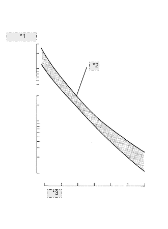
| *1 | Resistance |
| *2 | Acceptable |
| *3 | Temp. |
| DTC No. | DTC Detection Condition
|
Trouble Area |
|---|---|---|
| P0712 |
|
|
| P0713 |
|
|
MONITOR DESCRIPTION
These DTCs indicate an open or short in the automatic transmission fluid (ATF) temperature sensor circuit. The automatic transmission fluid (ATF) temperature sensor converts ATF temperature to an electrical resistance value. Based on the resistance, the TCM determines the ATF temperature, and the TCM detects an open or short in the ATF temperature circuit. If the resistance value of the ATF temperature is less than 0.049 V or more than 4.932 V , the TCM interprets this as a fault in the ATF sensor or wiring. The TCM will turn on the MIL and store the DTC.
WIRING DIAGRAM
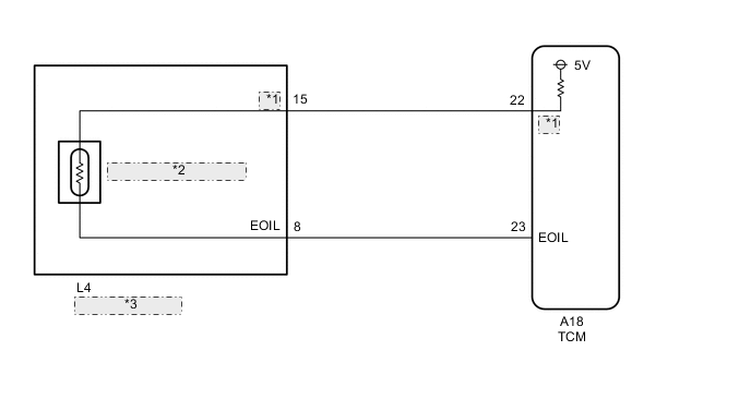
| *1 | OIL |
| *2 | ATF Temperature Sensor |
| *3 | Transmission Wire |
CAUTION / NOTICE / HINT
Note
Perform the universal trip to clear permanent DTCs Click here.
-
DATA LIST
Tech Tips
Using the GTS to read the Data List allows the values or states of switches, sensors, actuators and other items to be read without removing any parts. This non-intrusive inspection can be very useful because intermittent conditions or signals may be discovered before parts or wiring is disturbed. Reading the Data List information early in troubleshooting is one way to save diagnostic time.
Note
In the table below, the values listed under "Normal Condition" are reference values. Do not depend solely on these reference values when deciding whether a part is faulty or not.
-
Warm up the engine.
-
Turn the ignition switch off.
-
Connect the GTS to the DLC3.
-
Turn the ignition switch ON.
-
Turn the GTS on.
-
Enter the following menus: Powertrain / ECT / Data List.
-
According to the display on the GTS, read the "Data List".
Item Measurement Item/
Range (display)
Normal Condition A/T Oil Temperature 1 ATF Temp. Sensor Value/
min.: -40°C (-40°F)
max.: 215°C (419°F)
-
After Stall Test;
Approx. 80°C (176°F)
-
Equal to ambient temperature when cold soak
Tech Tips
When DTC P0712 is output and GTS output is -40°C (-40°F) or more, there is a short circuit.
When DTC P0713 is output and GTS output is 171°C (340°F), there is an open circuit.
Temperature Displayed Malfunction 171°C (340°F) Open circuit -40°C (-40°F) or more Short circuit -
-
PROCEDURE
-
INSPECT TRANSMISSION WIRE (ATF TEMPERATURE SENSOR)
-
Disconnect the A18 TCM connector.
-
Measure the resistance according to the value(s) in the table below.
Standard resistance Tester Connection Condition Specified Condition A18-22(OIL) - A18-23(EOIL) Always 79 Ω to 156 kΩ -
Connect the A18 TCM connector.
NG 
CHECK HARNESS AND CONNECTOR (TRANSMISSION WIRE - TCM) Click here
OK 
-
-
REPLACE TCM
-
Replace the TCM Click here.
NEXT 
PERFORM THE RESET MEMORY Click here
-
-
CHECK HARNESS AND CONNECTOR (TRANSMISSION WIRE - TCM)
-
Disconnect the A18 TCM connector.
-
Disconnect the L4 transmission wire connector.
-
Measure the voltage according to the value(s) in the table below.
Standard voltage Tester Connection Condition Specified Condition L4-8(EOIL) - Body ground Ignition switch ON Below 1 V L4-15(OIL) - Body ground Ignition switch ON Below 1 V -
Measure the resistance according to the value(s) in the table below.
Standard resistance Tester Connection Condition Specified Condition A18-22(OIL) - L4-15(OIL) Always Below 1 Ω A18-23(EOIL) - L4-8(EOIL) Always Below 1 Ω L4-8(EOIL) - Body ground Always 10 kΩ or higher L4-15(OIL) - Body ground Always 10 kΩ or higher -
Connect the A18 TCM connector.
-
Connect the L4 transmission wire connector.
OK
REPAIR OR REPLACE TRANSMISSION WIRE Click here
NG
REPAIR OR REPLACE HARNESS OR CONNECTOR
-