AFS ECU (for RHD) REMOVAL

-
PRECAUTION
Note
After turning the power switch off, waiting time may be required before disconnecting the cable from the battery terminal. Therefore, make sure to read the disconnecting the cable from the battery terminal notice before proceeding with work Click here.
-
REMOVE LUGGAGE COMPARTMENT FLOOR MAT
-
Remove the luggage compartment floor mat.
-
-
REMOVE LUGGAGE COMPARTMENT TRIM COVER LH
-
Remove the luggage compartment trim cover LH.
-
-
DISCONNECT CABLE FROM AUXILIARY BATTERY NEGATIVE TERMINAL
Note
When disconnecting the cable, some systems need to be initialized after the cable is reconnected Click here.
-
REMOVE FRONT DOOR SCUFF PLATE LH
-
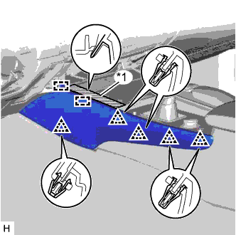
Place your hands on the inner portion of the front door scuff plate LH and detach the 2 claws labeled A, 6 claws labeled B and 2 claws labeled C in the order shown in the illustration.
-
Raise the front door scuff plate LH to detach the 4 clips on the outer side and remove it.
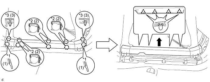
Text in Illustration *1 Claw A *2 Claw B *3 Claw C - -
-
-
REMOVE FRONT DOOR OPENING TRIM COVER LH
-
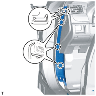
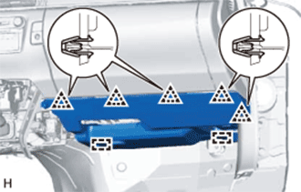
Detach the 5 claws and remove the front door opening trim cover LH.
-
-
REMOVE INSTRUMENT SIDE PANEL LH
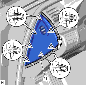
Text in Illustration *1 Protective Tape
-
Put protective tape around the instrument side panel LH.
-
Using a moulding remover, detach the 7 clips and remove the instrument side panel LH.
-
-
REMOVE CENTER INSTRUMENT CLUSTER FINISH PANEL
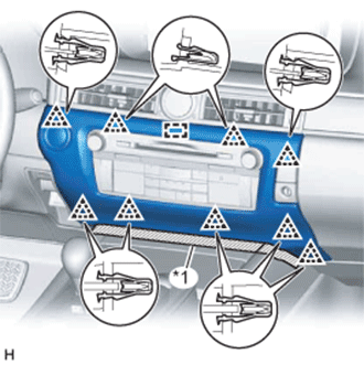
Text in Illustration *1 Protective Tape
-
Put protective tape around the center instrument cluster finish panel.
-
Detach the 9 clips and guide.
-
Disconnect the connector and remove the center instrument cluster finish panel.
-
-
REMOVE INSTRUMENT PANEL FINISH PANEL END LH
Text in Illustration *1 Protective Tape
-
Put protective tape around the instrument panel finish panel end LH.
-
Detach the 5 clips and 2 guides and remove the instrument panel finish panel end LH.
-
-
REMOVE NO. 2 INSTRUMENT PANEL UNDER COVER SUB-ASSEMBLY
-
Detach the 5 clips and 2 guides.
-
Disconnect the connectors, detach the clamp and remove the No. 2 instrument panel under cover sub-assembly.
-
-
REMOVE GLOVE COMPARTMENT DOOR ASSEMBLY
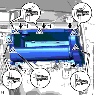
Text in Illustration *1 Screw <A> *2 Bolt <E>
-
Remove the 3 screws <A> and 2 bolts <E>.
-
Detach the 6 clips.
-
Disconnect the connectors, detach the clamp and remove the glove compartment door assembly.
-
-
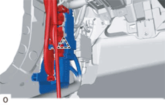
REMOVE ACCELERATION SENSOR ASSEMBLY
-
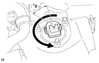
Text in Illustration *a 40° Turn the absorber control actuator counterclockwise 40° to remove it from the front shock absorber with coil spring.
-
-
REMOVE HEADLIGHT SWIVEL ECU ASSEMBLY
-
Detach the clip and remove the connector.
-
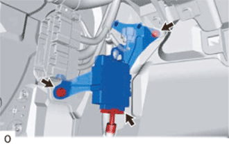
Remove the bolt, nut and headlight swivel ECU assembly.
-
Disconnect the connector.
-