METER / GAUGE SYSTEM Hybrid System Indicator Malfunction
DESCRIPTION
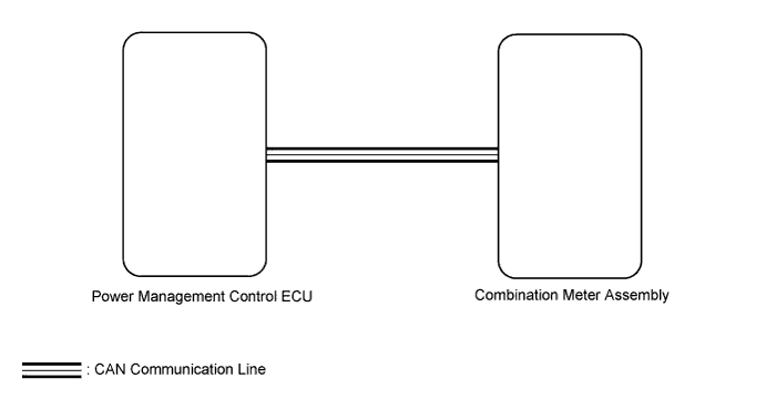
A hybrid system indicator is adopted for this vehicle. In this circuit, the meter CPU receives eco-zone indicator level signal from the power management control ECU via the CAN communication line. The meter CPU controls the operation of the hybrid system indicator according to the eco-zone indicator level signal received from the power management control ECU via the CAN communication line.
WIRING DIAGRAM
INSPECTION PROCEDURE
PROCEDURE
-
CHECK CAN COMMUNICATION SYSTEM
-
Check if a CAN communication DTC is output.
-
for LHD Click here.
-
for RHD Click here.
Result Result Proceed to CAN communication DTC is not output A CAN communication DTC is output (for LHD) B CAN communication DTC is output (for RHD) C
-
B 
GO TO CAN COMMUNICATION SYSTEM Click here
C
GO TO CAN COMMUNICATION SYSTEM Click here
A 
-
-
PERFORM ACTIVE TEST USING GTS (HV SYSTEM INDICATOR)
-
Use the Active Test to check the operation of the hybrid system indicator Click here.
Combination Meter Tester Display Test Part Control Range Diagnostic Note HV System Indicator Hybrid system Indicator MIN, -50, 0, 100, 200, 300, 400 or MAX (%) - OK Hybrid system indicator indication is normal.
NG
REPLACE COMBINATION METER ASSEMBLY Click here
OK
-
-
READ VALUE USING GTS (HYBRID SYSTEM INDICATOR)
-
Use the Data List to check the hybrid system indicator Click here.
Combination Meter Tester Display Test Part Control Range Diagnostic Note Hybrid System Indicator Hybrid system indicator value / Min.: -512 %, Max.: 511 % -512 to 511 % - OK Hybrid system indicator value displayed on the Techstream is almost the same as hybrid system indicator indication.
NG
GO TO HYBRID CONTROL SYSTEM Click here
OK
-
-
CHECK COMBINATION METER ASSEMBLY
-
Replace the combination meter assembly with a new or normally functioning one Click here.
-
Check the hybrid system indicator operation.
OK The operation of the hybrid system indicator returns to normal.
NG
REPLACE POWER MANAGEMENT CONTROL ECU Click here
OK 
END (COMBINATION METER ASSEMBLY WAS DEFECTIVE)
-