THEFT DETERRENT SYSTEM Tilt Sensor Circuit
DESCRIPTION
-
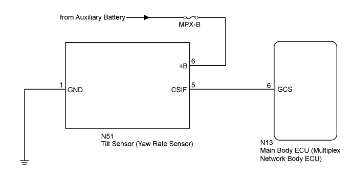
The main body ECU (multiplex network body ECU) operates the tilt sensor (yaw rate sensor) via the CSIF communication line. The tilt sensor (yaw rate sensor) sends information regarding changes in the vehicle tilt angle to the main body ECU (multiplex network body ECU). The main body ECU (multiplex network body ECU) checks whether the vehicle body is being tilted without authorization.
WIRING DIAGRAM
INSPECTION PROCEDURE
Note
-
If the main body ECU (multiplex network body ECU) is replaced, refer to the Service Bulletin.
-
When replacing the tilt sensor (yaw rate sensor), perform zero point calibration Click here.
-
Inspect the fuses for circuits related to this system before performing the following inspection procedure.
PROCEDURE
-
READ VALUE USING GTS (TILT SENSOR)
-
Connect the GTS to the DLC3.
-
Turn the power switch on (IG).
-
Turn the GTS on.
-
Enter the following menus: Body Electrical / Main Body / Data List.
-
According to the display on the GTS, read the Data List.
Main Body (Main Body ECU [Multiplex Network Body ECU]) Tester Display Measurement Item/Range Normal Condition Diagnostic Note Tilt Sensor Status of the tilt sensor detection / ON or OFF ON: Tilt sensor detected
OFF: Tilt sensor not detected
- Note
After setting the theft deterrent system, wait 30 seconds or more (until the vehicle is in the armed state), tilt the vehicle and confirm the Data List (jack up the vehicle so that the tires are in the air).
Tech Tips
When performing the above inspection, have the electrical key transmitter in the vehicle exterior detection area to perform certification (this prevents the alarm from sounding).
OK The display on the GTS changes according to the detection condition of the tilt sensor (yaw rate sensor).
NG 
CHECK TILT SENSOR (YAW RATE SENSOR) (CSIF) Click here
OK 
PROCEED TO NEXT CIRCUIT INSPECTION SHOWN IN PROBLEM SYMPTOMS TABLE Click here
-
-
CHECK TILT SENSOR (YAW RATE SENSOR) (CSIF)
-
Using an oscilloscope, check the waveform.
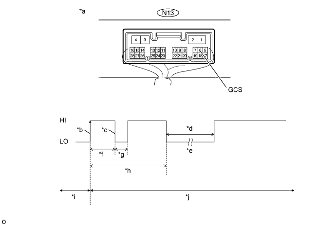
Text in Illustration *a Component with harness connected
(Main body ECU [multiplex network body ECU])
*b CSIF Initial Signal *c CSIF Initial Response *d Approximately 1.0 seconds *e Initial Diagnosis *f Approximately 1.0 to 1.6 seconds *g Approximately 0.05 seconds *h Approximately 5.5 seconds *i Disarmed State *j Arming Preparation State Measurement Condition Tester Connection Content Tester Connection N13-6 (GCS) - Body ground Tool Setting 2 V/DIV., 100 ms./DIV. Condition Theft deterrent system is set (system changes from disarmed state to arming preparation state) Tech Tips
-
If the tilt sensor (yaw rate sensor) is normal, an initial response is output in response to the HI input from the main body ECU (multiplex network body ECU).
-
If the waveform output remains LO, there may be a problem with the main body ECU (multiplex network body ECU), as there is no input from the main body ECU (multiplex network body ECU).
OK The waveform displays properly (HI is 6.5 V or higher and LO is below 1 V). -
NG 
REPLACE MAIN BODY ECU (MULTIPLEX NETWORK BODY ECU) Click here
OK 
-
-
CHECK HARNESS AND CONNECTOR (TILT SENSOR [YAW RATE SENSOR] - MAIN BODY ECU [MULTIPLEX NETWORK BODY ECU] AND BODY GROUND)
-
Disconnect the N51 tilt sensor (yaw rate sensor) connector.
-
Disconnect the N13 main body ECU (multiplex network body ECU) connector.
-
Measure the resistance according to the value(s) in the table below.
Standard Resistance Tester Connection Condition Specified Condition N51-5 (CSIF) - N13-6 (GCS) Always Below 1 Ω N51-1 (GND) - Body ground Always Below 1 Ω N51-5 (CSIF) - Body ground Always 10 kΩ or higher
NG
REPAIR OR REPLACE HARNESS OR CONNECTOR
OK
REPLACE TILT SENSOR (YAW RATE SENSOR) Click here
-