ELECTRONICALLY CONTROLLED BRAKE SYSTEM CALIBRATION

-
DESCRIPTION
-
After replacing any VSC related components or performing wheel alignment adjustment, clear and read the sensor calibration data.
-
Follow the chart below to perform calibration.
Part to be Replaced / Operation Necessary Operation Skid control ECU assembly Yaw rate and acceleration sensor zero point calibration Yaw rate sensor
-
Clearing zero point calibration data
-
Yaw rate and acceleration sensor zero point calibration
Wheel alignment adjustment
-
Clearing zero point calibration data
-
Yaw rate and acceleration sensor zero point calibration
-
-
OBTAIN ZERO POINT OF YAW RATE AND ACCELERATION SENSOR (When Using the GTS)
Note
-
While obtaining the zero points, keep the vehicle stationary and do not vibrate, tilt, move, or shake it. (Do not turn the power switch on (READY).)
-
Be sure to perform this procedure on a level surface (with an inclination of less than 1 degree).
-
Clear the zero point calibration data.
-
Turn the power switch off.
-
Check that the steering wheel is centered.
-
Check that the shift lever is in P.
-
Connect the GTS to the DLC3.
-
Turn the power switch on (IG).
-
Turn the GTS on.
-
Select the skid control ECU assembly and clear the zero point calibration data using the GTS. Enter the following menus: Chassis / ABS/VSC/TRC / Utility / Reset Memory.
-
Turn the power switch off.
Note
If the power switch is turned on (IG) for more than 15 seconds with the shift lever in P after the zero points of the yaw rate and acceleration sensor have been cleared, only the zero point of the yaw rate sensor will be stored. If the vehicle is driven under these conditions, the skid control ECU assembly will store the zero point calibration for the acceleration sensor as not being completed. The skid control ECU assembly will then also indicate this as a malfunction of the VSC system using the indicator light.
-
-
Perform the zero point calibration of the yaw rate and acceleration sensor.
-
Turn the power switch off.
-
Check that the steering wheel is centered.
-
Check that the shift lever is in P.
Note
DTCs C1210 (Zero Point Calibration of Yaw Rate Sensor Undone) and C1336 (Zero Point Calibration of Acceleration Sensor Undone) will be stored if the shift lever is not in P.
-
Connect the GTS to the DLC3.
-
Turn the power switch on (IG).
-
Turn the GTS on.
-
Switch the skid control ECU assembly to Test Mode using the GTS. Enter the following menus: Chassis / ABS/VSC/TRC / Utility / Test Mode.
-
After Test Mode has been entered, keep the vehicle stationary on a level surface for 4 seconds or more.
-
Check that the ABS warning, brake warning / yellow (minor malfunction) and slip indicator lights come on for several seconds and then blink in Test Mode.
Tech Tips
-
If the ABS warning, brake warning / yellow (minor malfunction) and slip indicator lights do not blink, perform zero point calibration again.
-
The zero point calibration is performed only once after the system enters Test Mode.
-
Calibration cannot be performed again until the stored data is cleared.
-
-
Turn the power switch off and disconnect the GTS.
-
-
-
OBTAIN ZERO POINT OF YAW RATE AND ACCELERATION SENSOR (When not Using the GTS)
Note
-
While obtaining the zero points, keep the vehicle stationary and do not vibrate, tilt, move, or shake it. (Do not turn the power switch on (READY).)
-
Be sure to perform this procedure on a level surface (with an inclination of less than 1 degree).
-
Clear the zero point calibration data.
-
Turn the power switch off.
-
Check that the steering wheel is centered.
-
Check that the shift lever is in P.
-
Turn the power switch on (IG).
-
Check that the initial check is completed.
-
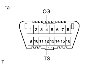
Text in Illustration *a Front view of DLC3 Using SST, connect and disconnect terminals TS and CG of the DLC3 4 times or more within 8 seconds.
- SST
- 09843-18040
-
Check that no codes other than ABS code 42, VSC code 45 and electronically controlled brake system code 48, 66, or 95 are stored in the diagnostic system.
-
How to read DTCs:
Diagnostic trouble codes are represented by the number of blinks of a warning light. For example, code 21 would be shown by 2 blinks, a pause of 1.5 seconds, and then 1 blink.
-
If one code is detected:
The light repeats the same code after a pause of 4 seconds.
-
If multiple codes are detected:
The light outputs one code after another with a 2.5-second pause between each code. When all codes have been output, there is a 4-second pause and then the light begins to output the codes again.
-
The ABS warning, brake warning / yellow (minor malfunction) and slip indicator lights do not indicate a normal system code.
Note
If the power switch is turned on (IG) for more than 15 seconds with the shift lever in P after the zero points of the yaw rate and acceleration sensor have been cleared, only the zero point of the yaw rate sensor will be stored. If the vehicle is driven under these conditions, the skid control ECU assembly will store the zero point calibration for the acceleration sensor as not being completed. The skid control ECU assembly will then also indicate this as a malfunction of the VSC system using the indicator light.
-
-
-
Perform the zero point calibration of the yaw rate and acceleration sensor.
-
Turn the power switch off.
-
Check that the steering wheel is centered.
-
Check that the shift lever is in P.
Note
DTCs 36 (Zero Point Calibration of Yaw Rate Sensor Undone) and 98 (Zero Point Calibration of Acceleration Sensor Undone) will be recorded if the shift lever is not in P.
-
Text in Illustration *a Front view of DLC3 Using SST, connect terminals TS and CG of the DLC3.
- SST
- 09843-18040
-
Turn the power switch on (IG).
-
After Test Mode has been entered, keep the vehicle stationary on a level surface for 4 seconds or more.
-
Check that the ABS warning, brake warning / yellow (minor malfunction) and slip indicator lights come on for several seconds and then blink in Test Mode.
Tech Tips
-
If the ABS warning, brake warning / yellow (minor malfunction) and slip indicator lights do not blink, perform zero point calibration again.
-
The zero point calibration is performed only once after the system enters Test Mode.
-
Calibration cannot be performed again until the stored data is cleared.
-
-
Turn the power switch off and disconnect SST from the DLC3.
-
-