AIR CONDITIONING SYSTEM, Diagnostic DTC:P0AA6-611

| DTC Code | DTC Name |
|---|---|
| P0AA6-611 | Hybrid Battery Voltage System Isolation Fault |
DESCRIPTION
The DTC is stored if there is insulation trouble with the high voltage circuit in the air conditioning system. Possible causes are poor insulation in the compressor with motor assembly, or mixing of any oil other than ND-OIL 11 in the refrigerant cycle.
A high voltage motor is built into the electrical compressor and is cooled directly with refrigerant. Compressor oil (ND-OIL 11) with high insulation performance is used because a leakage of electrical power may occur if regular compressor oil (ND-OIL 8) is used.
| DTC Code | DTC Detection Condition | Trouble Area |
|---|---|---|
| P0AA6-611 | High voltage system insulation malfunction |
|
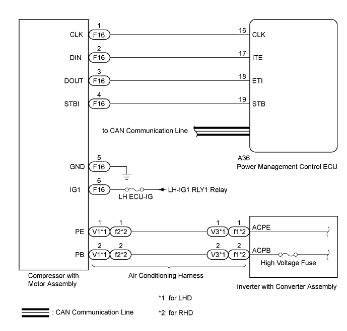
WIRING DIAGRAM
INSPECTION PROCEDURE
CAUTION:
-
When performing this DTC troubleshooting, use either a tool wrapped with vinyl insulation tape or a insulated tool. (It is extremely dangerous when a high voltage charge passes through a non-insulated tool causing a short.)
-
Before inspecting the high voltage system or disconnecting the low voltage connector of the inverter with converter assembly, take safety precautions such as wearing insulated gloves and removing the service plug grip to prevent electrical shocks. After removing the service plug grip, put it in your pocket to prevent other technicians from accidentally reconnecting it while you are working on the high voltage system Click here.
-
After removing the service plug grip, wait for at least 10 minutes before touching any of the high voltage connectors or terminals. After waiting for 10 minutes, check the voltage at the terminals in the inspection point in the inverter with converter assembly. The voltage should be 0 V before beginning work Click here.
Tech Tips
Waiting for at least 10 minutes is required to discharge the high voltage capacitor inside the inverter with converter assembly.
Note
-
After turning the power switch off, waiting time may be required before disconnecting the cable from the negative (-) auxiliary battery terminal. Therefore, make sure to read the disconnecting the cable from the negative (-) auxiliary battery terminal notices before proceeding with work Click here.
-
Inspect the fuses for circuits related to this system before performing the following inspection procedure.
-
Electrical insulation performance may decrease significantly if even a small amount of oil other than ND-OIL 11 is used (or enters) in the refrigerant cycle, causing the DTC P0AA6-611 to be output.
-
If other oil is accidentally used and a DTC P0AA6-611 is output, collect the oil in the refrigerant cycle into the compressor and replace it with ND-OIL 11 to increase the ND-OIL 11 ratio amount.
-
Replace the main components (evaporator, condenser, and compressor) if a large amount of oil other than ND-OIL 11 enters the system. Failing to do so may cause electrical insulation performance to remain low, causing the DTC P0AA6-611 to be output.
Tech Tips
If it can be confirmed that any compressor oil other than ND-OIL 11 has been used in the vehicle, replace the air conditioning cycle.
-
The hybrid control system and air conditioning system output DTCs separately. Inspect DTCs following the diagnosis procedure for the hybrid control system first if any DTCs from those systems are output simultaneously Click here.
Tech Tips
When measuring insulation resistance using a megohmmeter, set the megohmmeter to 500 V.
PROCEDURE
-
CHECK CAN COMMUNICATION SYSTEM
-
Use the GTS to check if the CAN communication system is functioning normally.
-
for LHD: Click here.
-
for RHD: Click here.
Result Result Proceed to CAN DTC is not output A CAN DTC is output (for LHD) B CAN DTC is output (for RHD) C -
B 
GO TO CAN COMMUNICATION SYSTEM Click here
C
GO TO CAN COMMUNICATION SYSTEM Click here
A 
-
-
INSPECT COMPRESSOR WITH MOTOR ASSEMBLY
CAUTION:
Be sure to wear insulated gloves.
-
Clear the DTCs Click here.
-
Turn the power switch on (Ready).
-
Prepare the vehicle according to the table below for 3 minutes.
Item Condition Blower Speed Hi Temperature Setting LO A/C Switch On -
Turn the power switch off.
-
Remove the service plug grip Click here.
CAUTION:
Do not touch the high voltage connectors or terminals for 10 minutes after the service plug grip is removed.
Note
After removing the service plug grip, turning the power switch on (Ready) may cause a malfunction. Do not turn the power switch on (Ready) with the service plug grip removed.
-

Disconnect the V1*1 or f1*2 compressor with motor assembly connector.
-
*1: for LHD
-
*2: for RHD
-
-
Using a megohmmeter, measure the resistance according to the value(s) in the table below.
CAUTION:
Be sure to set the megohmmeter to 500 V when performing this test. Using a setting higher than 500 V can result in damage to the component being inspected.
Standard Resistance Tester Connection Condition Specified Condition 1 (PE) - Body ground Always 2 MΩ or higher 2 (PB) - Body ground Always 2 MΩ or higher
NG
REPLACE COMPRESSOR WITH MOTOR ASSEMBLY Click here
OK
-
-
INSPECT COMPRESSOR WITH MOTOR ASSEMBLY
CAUTION:
Be sure to wear insulated gloves.
-
Reconnect the V1*1 or f1*2 connector to the compressor with motor assembly.
-
*1: for LHD
-
*2: for RHD
-
-
Install the service plug grip Click here.
-
Turn the power switch on (Ready).
-
Prepare the vehicle according to the table below for 10 minutes.
Item Condition Blower Speed Lo Temperature Setting 25°C (77°F) A/C Switch On -
Turn the power switch off.
-
Using a spot cooler or other tools, cool down the compressor with motor assembly for 30 minutes, or leave the vehicle overnight before inspection.
Note
Do not operate the compressor before inspection.
-
Remove the service plug grip Click here.
CAUTION:
Do not touch the high voltage connectors or terminals for 10 minutes after the service plug grip is removed.
Note
After removing the service plug grip, turning the power switch on (Ready) may cause a malfunction. Do not turn the power switch on (Ready) with the service plug grip removed.
-
Disconnect the V1*1 or f1*2 compressor with motor assembly connector.
-
*1: for LHD
-
*2: for RHD
-
-
Using a megohmmeter, measure the resistance according to the value(s) in the table below.
CAUTION:
Be sure to set the megohmmeter to 500 V when performing this test. Using a setting higher than 500 V can result in damage to the component being inspected.
Standard Resistance Tester Connection Condition Specified Condition 1 (PE) - Body ground Always 3 MΩ or higher 2 (PB) - Body ground Always 3 MΩ or higher Note
If the results are out of the specified range, replace the compressor without operating it.
NG
REPLACE AIR CONDITIONING CYCLE
OK 
REPLACE COMPRESSOR WITH MOTOR ASSEMBLY Click here
-