AIR CONDITIONING UNIT INSTALLATION

Tech Tips
-
Use the same procedure for RHD and LHD vehicles.
-
The procedure listed below is for LHD vehicles.
-
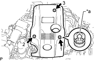
INSTALL AIR CONDITIONING UNIT
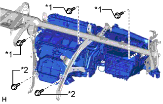
Text in Illustration *1 Bolt *2 Screw
-
Install the air conditioning unit with the 3 bolts and 2 screws.
- Torque:
- for bolt
- 9.8 N*m { 100 kgf*cm, 87 in.*lbf }
-
-
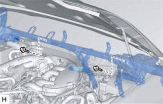
INSTALL INSTRUMENT PANEL REINFORCEMENT ASSEMBLY WITH AIR CONDITIONING UNIT ASSEMBLY
-
Install the instrument panel reinforcement assembly with air conditioning unit assembly.
-
Using a 12 mm hexagon wrench, tighten the 3 collars.
-
Install the 9 bolts.
- Torque:
- for bolt A
- 20 N*m { 204 kgf*cm, 15 ft.*lbf }
- for bolt B
- 21 N*m { 214 kgf*cm, 15 ft.*lbf }
-
Install the 6 caps.
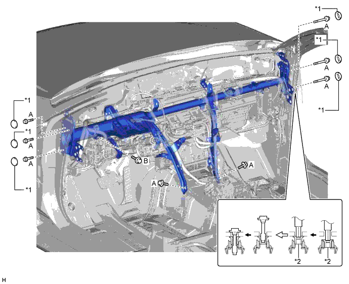
Text in Illustration *1 Cap *2 Collar -
Install the nut.
- Torque:
- 9.8 N*m { 100 kgf*cm, 87 in.*lbf }
-
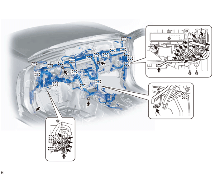
Install the bolts and nuts.
-
Attach the clamps and connect the connectors.
-
Install the 2 bolts.
- Torque:
- 10 N*m { 102 kgf*cm, 7 ft.*lbf }
-
Install the 2 grommets.
-
-
INSTALL QUICK HEATER ASSEMBLY (w/ PTC Heater)
-
Attach the 2 claws to install the quick heater assembly.
Note
If the claws of the quick heater assembly are damaged, install the quick heater assembly with 2 screws (90159-50327).
-
-
INSTALL AIR CONDITIONING AMPLIFIER ASSEMBLY
-
INSTALL AIR HOSE
-
Install the air hose.
-
-
INSTALL LOWER DEFROSTER NOZZLE ASSEMBLY
-
Attach the 3 claws to install the lower defroster nozzle assembly.
-
-
INSTALL STEERING COLUMN ASSEMBLY
-
INSTALL NO. 2 AIR DUCT SUB-ASSEMBLY
-
Install the No. 2 air duct sub-assembly with the screw.
-
-
INSTALL NO. 1 AIR DUCT SUB-ASSEMBLY
-
Install the No. 1 air duct sub-assembly with the clip.
-
-
INSTALL NO. 1 CONSOLE BOX DUCT
-
Install the No. 1 console box duct with the 2 clips.
-
-
INSTALL REAR NO. 3 AIR DUCT
-
Install the rear No. 3 air duct.
-
Attach the clamp.
-
-
INSTALL REAR NO. 1 AIR DUCT
-
Install the rear No. 1 air duct.
-
Attach the clamp.
-
-
INSTALL REAR NO. 2 AIR DUCT
-
Attach the 4 claws to install the rear No. 2 air duct.
-
Install the nut or clip.
Tech Tips
The rear No. 2 air duct is installed with a nut or clip.
-
-
INSTALL REAR NO. 4 AIR DUCT
-
Attach the 4 claws to install the rear No. 4 air duct.
-
Install the nut or clip.
Tech Tips
The rear No. 4 air duct is installed with a nut or clip.
-
-
INSTALL FRONT FLOOR CARPET ASSEMBLY
-
INSTALL REAR NO. 5 AIR DUCT
Tech Tips
Use the same procedure for both rear No. 5 air ducts.
-
Install the rear No. 5 air duct with the 2 screws.
-
-
INSTALL AIR DUCT PLUG
Tech Tips
Use the same procedure for both air duct plugs.
-
Attach the 4 claws to install the air duct plug.
-
-
INSTALL INSTRUMENT PANEL SAFETY PAD SUB-ASSEMBLY
-
INSTALL REAR SEAT ASSEMBLY
-
INSTALL FRONT SEAT ASSEMBLY
-
for Sports Seat Type:
-
for Luxury Seat Type:
-
for Standard Seat Type:
-
-
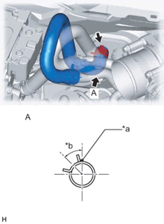
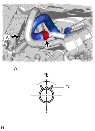
INSTALL HEATER WATER INLET HOSE A (for 2GR-FXE)
-
Text in Illustration *a for LHD: Brown Marking
for RHD: Purple Marking
*b 90° +/- 15° Connect the heater water inlet hose A (unit side) as shown in the illustration.
-
-
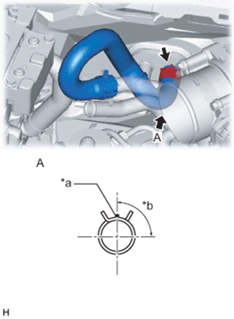
INSTALL HEATER WATER OUTLET HOSE A (for 2GR-FXE)
-
Text in Illustration *a for LHD: Blown Marking
for RHD: Purple Marking
*b 45°+/- 15° Connect the heater water outlet hose A (unit side) and attach the clip.
-
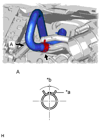
Text in Illustration *a Blue Marking *b 0°+/- 15° Connect the heater water outlet hose A (engine side) and attach the clip to install the heater water outlet hose A.
-
Text in Illustration *a Yellow Marking *b 0°+/- 15° Connect the heater water inlet hose A (engine side) and attach the clip to install the heater water inlet hose A.
-
Install the water hose set.
-
-
CONNECT HEATER WATER INLET HOSE A (for 2AR-FSE)
-
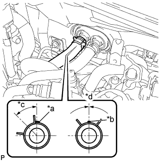
Text in Illustration *a Brown Marking 5 mm *b Brown Marking 2 mm *c 45° +/- 15° *d 0° +/- 15° Connect the heater water inlet hose A and attach the clip.
-
-
CONNECT HEATER WATER OUTLET HOSE A
-
Connect the heater water outlet hose A and attach the clip.
-
-
CONNECT AIR CONDITIONING TUBE ASSEMBLY
-
Remove the vinyl tape attached to the air conditioning tube assembly.
-
Sufficiently apply compressor oil to 2 new O-rings and the fitting surface of the air conditioning tube assembly.
Compressor oil ND-OIL 11 or equivalent -
Install the 2 O-rings to the air conditioning tube assembly.
-
Connect the air conditioning tube assembly.
Note
After the connection, check that the claw of the piping clamp is attached.
-
Text in Illustration *1 Plate Attach the plate as shown in the illustration and install the bolt.
- Torque:
- 9.8 N*m { 100 kgf*cm, 87 in.*lbf }
-
-
INSTALL FRONT WIPER MOTOR
-
CONNECT CABLE FROM AUXILIARY BATTERY NEGATIVE TERMINAL
Note
When disconnecting the cable, some systems need to be initialized after the cable is reconnected Click here.
-
INSTALL LUGGAGE COMPARTMENT TRIM COVER LH
-
Install the luggage compartment trim cover LH.
-
-
INSTALL LUGGAGE COMPARTMENT FLOOR MAT
-
Install the luggage compartment floor mat.
-
-
INSTALL AIR CLEANER CAP WITH AIR CLEANER HOSE (for 2GR-FXE)
-
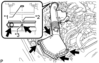
Text in Illustration *1 Bump *2 Cutout *3 Protrusion Install the air cleaner cap with air cleaner hose assembly with the 4 clamps and hose clamp.
- Torque:
- 4.0 N*m { 41 kgf*cm, 35 in.*lbf }
Note
-
Insert the protrusion on the throttle body side hose into the hole of the hose clamp.
-
Align the bump on the throttle body side with the cutout in the hose.
-
Connect the VSV hose to the air cleaner hose.
-
Connect the mass air flow meter connector and clamp to the air cleaner.
-
-
ADD ENGINE COOLANT
CAUTION:
Do not remove the radiator cap or reservoir tank cap while the engine and radiator are still hot. Pressurized hot engine coolant and steam may be released and cause serious burns.
Tech Tips
Before starting the engine to warm up the engine, turn the A/C switch off.
-
Tighten the 2 cylinder block drain cock plugs.
- Torque:
- 13 N*m { 130 kgf*cm, 9 ft.*lbf }
-
Tighten the radiator drain cock plug.
-
Remove the reservoir tank cap and radiator cap.
-
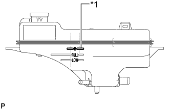
Text in Illustration *1 B Line Add coolant through the radiator reservoir tank filler opening until the coolant reaches the "B" line and install the reservoir tank cap.
Standard Capacity Radiator Core Thickness [mm] Specified Condition 16 9.4 liters (9.9 US qts, 8.3 Imp. qts) 27 9.9 liters (10.5 US qts, 8.7 Imp. qts) Note
Never use water as a substitute for engine coolant.
Tech Tips
TOYOTA vehicles are filled with TOYOTA SLLC at the factory. In order to avoid damage to the engine cooling system and other technical problems, only use TOYOTA SLLC or similar high quality ethylene glycol based non-silicate, non-amine, non-nitrite, non-borate coolant with long-life hybrid organic acid technology (coolant with long-life hybrid organic acid technology is a combination of low phosphates and organic acids).
-
Add engine coolant to the coolant filler opening and install the radiator cap.
Tech Tips
Press the No. 1 and No. 2 radiator hoses several times by hand, and then check the level of the coolant.
-
Put the engine in inspection mode Click here. [*1]
-
Warm up the engine until the thermostat opens. While the thermostat is open, circulate the coolant for several minutes. [*2]
CAUTION:
-
Wear protective gloves.
-
Be careful as the radiator hoses are hot.
-
Keep your hands away from the radiator fans.
Note
-
Immediately after starting the engine, if the radiator reservoir tank does not have any coolant, perform the following: 1) stop the engine, 2) wait until the coolant has cooled down, and 3) add coolant.
-
Do not start the engine when there is no coolant in the radiator reservoir tank.
-
Make sure that the needle does not show an abnormally high temperature.
-
If there is not enough coolant, the engine may overheat.
Tech Tips
-
Press the No. 1 and No. 2 radiator hoses several times by hand, and then check the level of the coolant.
-
The thermostat open timing can be confirmed by pressing the No. 2 radiator hose by hand, and checking when the engine coolant starts to flow inside the hose.
-
-
Stop the engine, and wait until the engine coolant cools down to ambient temperature. [*3]
-
Check the coolant level in the radiator reservoir tank. [*4]
Tech Tips
-
If the coolant level is below the "Low" line, add coolant through the radiator reservoir tank filler opening until the coolant reaches the "B" line and repeat steps [*1] through [*4].
-
If the coolant level is above the "FULL" line, drain coolant until the coolant level is between the "FULL" and "LOW" line.
-
-
-
CHARGE AIR CONDITIONING SYSTEM WITH REFRIGERANT
-
Perform vacuum purging using a vacuum pump or appropriate equipment.
-
Charge the air conditioning system with refrigerant.
Refrigerant type HFC-134a (R134a) 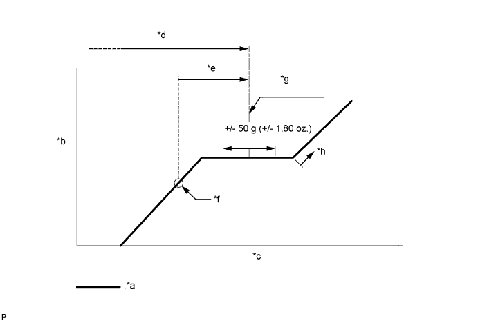
Text in Illustration *a Sub-cool System *b High Pressure *c Refrigerant Amount *d Standard charge amount *e Charge additional 100 g (3.5 oz.) *f Point where bubbles disappear *g Mean value in proper range *h Overcharged Standard charge amount for 2GR-FXE 450 to 550 g (15.9 to 19.4 oz.) for 2AR-FSE 520 to 620 g (18.3 to 21.8 oz.) - SST
- 09985-20010 ( 09985-02010, 09985-02050, 09985-02060, 09985-02070, 09985-02080, 09985-02090, 09985-02110, 09985-02130, 09985-02140, 09985-02150 )
Note
-
Do not turn the A/C switch on before charging the air conditioning system with refrigerant. Doing so may cause the compressor to work without refrigerant, resulting in overheating of the compressor.
-
The refrigerant amount should be checked by quantity (weight).
Tech Tips
Make sure that sufficient refrigerant is available to recharge the system when using a refrigerant recovery unit. Refrigerant recovery units are not always able to recover 100% of the refrigerant from an air conditioning system.
-
-
WARM UP COMPRESSOR
-
Keep the A/C switch on for at least 2 minutes to warm up the compressor.
Note
To prevent damage to the compressor, be sure to warm up the compressor when turning the air conditioning on after removing and installing air conditioning system lines (including the compressor).
-
-
INSPECT FOR COOLANT LEAK
CAUTION:
Do not remove the radiator cap or reservoir tank cap while the engine and radiator are still hot. Pressurized hot engine coolant and steam may be released and cause serious burns.
Note
Before performing each inspection, turn the A/C switch off.
-
Remove the reservoir tank cap.
-
Fill the radiator with coolant and attach a radiator cap tester.
-
Put the engine in inspection mode Click here.
-
Warm up the engine.
-
Using a radiator cap tester, increase the pressure inside the radiator to 137 kPa (1.4 kgf/cm2, 20 psi), and check that the pressure does not drop.
If the pressure drops, check the hoses, radiator and engine water pump for leaks. If no external leaks are found, check the heater core, cylinder block and cylinder head.
-
-
CHECK FOR REFRIGERANT GAS LEAK
-
After recharging the air conditioning system with refrigerant, check for refrigerant leaks using a halogen leak detector.
-
Carry out the test under the following conditions:
-
Power switch off.
-
Secure good ventilation (the halogen leak detector may react to volatile gases which are not refrigerant, such as gasoline vapor and exhaust gas).
-
Repeat the inspection 2 or 3 times.
-
Measure the pressure to make sure that there is some refrigerant remaining in the air conditioning system (pressure when the compressor is off: approx. 392 to 588 kPa (3.9 to 5.9 kgf/cm2, 57 to 85 psi)).
-
-
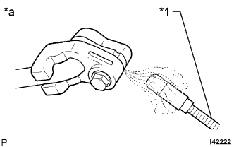
Text in Illustration *1 Halogen Leak Detector *a Check for Leak Using a halogen leak detector, check for refrigerant leaks from the air conditioning system.
-
If a refrigerant leak is not detected from the drain hose, remove the blower motor control from the cooling unit. Insert the halogen leak detector sensor into the unit and check for a leak.
-
Disconnect the pressure sensor connector and leave it for approximately 20 minutes. Bring the halogen leak detector close to the pressure sensor and check for a leak.
Tech Tips
When checking for leaks, the presence of oily dirt at a joint can indicate a leak.
-
-
INSTALL NO. 1 AIR CLEANER INLET
-
Install the No. 1 air cleaner inlet with the bolt.
- Torque:
- 5.0 N*m { 51 kgf*cm, 44 in.*lbf }
-
-
INSTALL ENGINE UNDER COVER
-
Install the engine under cover with the 13 screws and 3 clips.
-
-
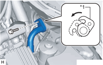
INSTALL V-BANK COVER SUB-ASSEMBLY (for 2GR-FXE)
-
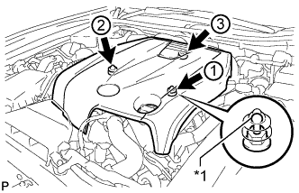
Text in Illustration *1 Tip (Round Portion) Attach the 3 clips in the order shown in the illustration to install the V-bank cover.
Note
-
Securely attach the clips.
-
If the clips are forcibly attached or struck with an object, they may be damaged.
-
Do not apply any oil to the tips (round portions).
-
-
-
INSTALL NO. 1 ENGINE COVER (for 2AR-FSE)
-
Text in Illustration *a Tip (Round Portion) Attach the 3 clips in the order shown in the illustration to install the No. 1 engine cover sub-assembly.
Note
-
Securely engage the clips.
-
If the clips are forcibly attached or struck with an object, they may be damaged.
-
-
-
INSTALL COOL AIR INTAKE DUCT SEAL
-
Install the cool air intake duct seal with the 7 clips.
-
-
INSTALL ENGINE ROOM SIDE COVER
-
Install the engine room side cover with the 4 clips.
-
-
CHECK SRS WARNING LIGHT