POWER STEERING SYSTEM (for 2GR-FXE), Diagnostic DTC:C1552/22, C1568/27

| DTC Code | DTC Name |
|---|---|
| C1552/22 | PIG Power Supply Voltage Malfunction |
| C1568/27 | DC-DC Converter |
DESCRIPTION
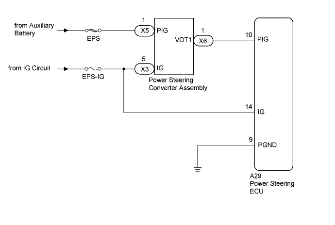
The power steering converter assembly steps down the HV battery voltage to approximately 46 V. This voltage is then supplied to the power steering ECU to operate the motors.
| DTC Code | Detection Condition | Trouble Area |
|---|---|---|
| C1552/22 | PIG power supply voltage malfunction |
|
| C1568/27 | Power steering converter inner circuit malfunction |
WIRING DIAGRAM
INSPECTION PROCEDURE
CAUTION:
-
Before inspecting the high-voltage system or disconnecting the low voltage connector of the power steering converter assembly, take safety precautions such as wearing insulated gloves and removing the service plug grip to prevent electrical shocks. After removing the service plug grip, put it in your pocket to prevent other technicians from accidentally reconnecting it while you are working on the high-voltage system.
-
After removing the service plug grip, wait for at least 10 minutes before touching any of the high-voltage connectors or terminals. After waiting for 10 minutes, check the voltage at the terminals in the inspection point in the inverter with converter assembly. The voltage should be 0 V before beginning work Click here.
Tech Tips
Waiting for at least 10 minutes is required to discharge the high-voltage capacitor inside the inverter with converter assembly.
Note
-
Inspect the fuses for circuits related to this system before performing the following inspection procedure.
-
After turning the power switch off, waiting time may be required before disconnecting the cable from the negative (-) auxiliary battery terminal. Therefore, make sure to read the disconnecting the cable from the negative (-) auxiliary battery terminal notices before proceeding with work Click here.
-
If the power steering ECU assembly is replaced a new one, perform assist map writing, clear the motor rotation angle sensor calibration value, initialize the motor rotation angle sensor value and calibrate the torque sensor zero point Click here.
PROCEDURE
-
CHECK CONNECTORS
CAUTION:
Be sure to wear insulated gloves.
-
Check that the service plug grip is not installed.
Note
After removing the service plug grip, do not turn the power switch on (READY), unless instructed by the repair manual because this may cause a malfunction.
-
Check the connection of the power steering ECU and power steering converter connectors.
-
Visually inspect the terminals of the power steering ECU and power steering converter connectors.
Result Result
Proceed to
Normal A Connectors not properly connected B Power steering ECU connector terminals abnormal C Power steering converter connector terminals abnormal D
B 
CONNECTOR CORRECTLY
C
REPLACE POWER STEERING ECU ASSEMBLY Click here
D
REPLACE POWER STEERING CONVERTER ASSEMBLY Click here
A 
-
-
READ VALUE USING GTS (MOTOR VOLTAGE)
-
Turn the power switch off.
-
Connect the GTS to the DLC3.
-
Turn the power switch on (READY).
-
Turn the GTS on.
-
Enter the following menus: Chassis / EMPS / Data List.
-
Select the item "Motor Voltage" in the Data List and read the value displayed on the GTS.
EMPS Tester Display Measurement Item/Range Normal Condition Diagnostic Note Motor Voltage Motor power source voltage/
Min.: 0.000 V
Max.: 98.000 V
Approximately 46 V The power steering is not in operation. Approximately 25 to 50 V The power steering is in operation. OK Normal condition value is displayed on the GTS.
NG 
CHECK HARNESS AND CONNECTOR (POWER STEERING CONVERTER PIG POWER SUPPLY) Click here
OK 
REPLACE POWER STEERING ECU ASSEMBLY Click here
-
-
CHECK HARNESS AND CONNECTOR (POWER STEERING CONVERTER PIG POWER SUPPLY)
CAUTION:
Be sure to wear insulated gloves.
-
Check that the service plug grip is not installed.
Note
After removing the service plug grip, do not turn the power switch on (READY), unless instructed by the repair manual because this may cause a malfunction.
-
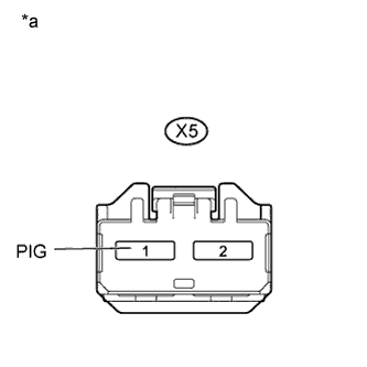
Text in Illustration *a Front view of wire harness connector
(to Power Steering Converter)
Disconnect the power steering converter connector.
-
Measure the voltage according to the value(s) in the table below.
Standard Voltage Tester Connection Condition Specified Condition X5-1 (PIG) - Body ground Always 11 to 14 V
NG
REPAIR OR REPLACE HARNESS OR CONNECTOR
OK
-
-
CHECK HARNESS AND CONNECTOR (POWER STEERING CONVERTER IG POWER SUPPLY)
CAUTION:
Be sure to wear insulated gloves.
-
Check that the service plug grip is not installed.
Note
After removing the service plug grip, do not turn the power switch on (READY), unless instructed by the repair manual because this may cause a malfunction.
-
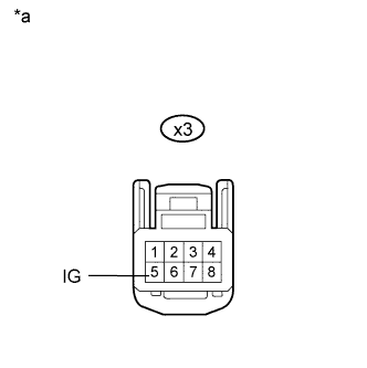
Text in Illustration *a Front view of wire harness connector
(to Power Steering Converter)
Disconnect the power steering converter connector.
-
Measure the voltage according to the value(s) in the table below.
Standard Voltage Tester Connection Switch Condition Specified Condition X3-5 (IG) - Body ground Power switch on (IG) 11 to 14 V
NG
REPAIR OR REPLACE HARNESS OR CONNECTOR
OK
-
-
CHECK HARNESS AND CONNECTOR (POWER STEERING ECU PIG POWER SUPPLY)
CAUTION:
Be sure to wear insulated gloves.
-
Check that the service plug grip is not installed.
Note
After removing the service plug grip, do not turn the power switch on (READY), unless instructed by the repair manual because this may cause a malfunction.
-
Disconnect the A29 power steering ECU connector.
-
Disconnect the X6 power steering converter connector.
-
Measure the resistance according to the value(s) in the table below.
Standard Resistance Tester Connection Condition Specified Condition A29-10 (PIG) - X6-1 (VOT1) Always Below 1 Ω A29-9 (PGND) - Body ground A29-10 (PIG) or X6-1 (VOT1) - Body ground Always 10 kΩ or higher
NG
REPAIR OR REPLACE HARNESS OR CONNECTOR
OK
-
-
CHECK POWER STEERING CONVERTER ASSEMBLY (VOT1)
CAUTION:
Be sure to wear insulated gloves.
-
Reconnect the power steering ECU connector.
-
Reconnect the power steering converter connector.
-
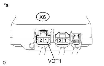
Text in Illustration *a Component with harness connected
(Power Steering Converter)
Measure the voltage according to the value(s) in the table below.
Standard Voltage Tester Connection Switch Condition Specified Condition X6-1 (VOT1) - Body ground Power switch on (READY) 25 to 50 V
NG
REPLACE POWER STEERING CONVERTER ASSEMBLY Click here
OK
-
-
CHECK POWER STEERING SYSTEM (OPERATION)
-
Turn the power switch on (READY) and check whether the power assistance operates.
Result Result Proceed to Power assistance is operating A Power assistance is not operating B
B
REPLACE POWER STEERING ECU ASSEMBLY Click here
A
USE SIMULATION METHOD TO CHECK Click here
-