AIR CONDITIONING SYSTEM, Diagnostic DTC:B1498/98

| DTC Code | DTC Name |
|---|---|
| B1498/98 | Communication Malfunction (A/C Inverter Local) |
DESCRIPTION
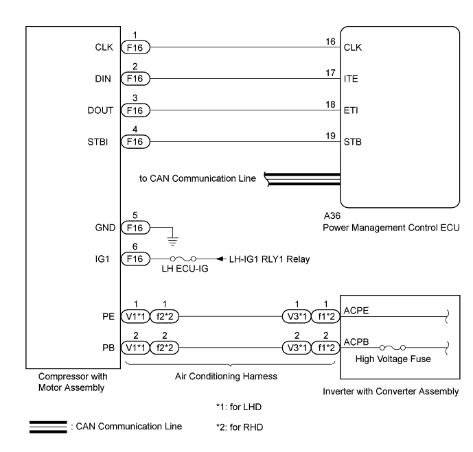
The power management control ECU and compressor with motor assembly transmit information to one another via a communication line. Compressor control is stopped and the DTC is stored if communication information is cut off or abnormal information occurs.
The DTC B1498/98 is also detected if high voltage power supplied from the inverter with converter assembly to the compressor control circuit is shut off.
This DTC will be stored as a history DTC.
| DTC Code | DTC Detection Condition | Trouble Area |
|---|---|---|
| B1498/98 |
|
|
WIRING DIAGRAM
INSPECTION PROCEDURE
CAUTION:
-
When performing this DTC troubleshooting, use either a tool wrapped with vinyl insulation tape or a insulated tool. (It is extremely dangerous when a high voltage charge passes through a non-insulated tool causing a short.)
-
Before inspecting the high voltage system or disconnecting the low voltage connector of the inverter with converter assembly, take safety precautions such as wearing insulated gloves and removing the service plug grip to prevent electrical shocks. After removing the service plug grip, put it in your pocket to prevent other technicians from accidentally reconnecting it while you are working on the high voltage system Click here.
-
After removing the service plug grip, wait for at least 10 minutes before touching any of the high voltage connectors or terminals. After waiting for 10 minutes, check the voltage at the terminals in the inspection point in the inverter with converter assembly. The voltage should be 0 V before beginning work Click here.
Tech Tips
Waiting for at least 10 minutes is required to discharge the high voltage capacitor inside the inverter with converter assembly.
Note
-
After turning the power switch off, waiting time may be required before disconnecting the cable from the negative (-) auxiliary battery terminal. Therefore, make sure to read the disconnecting the cable from the negative (-) auxiliary battery terminal notices before proceeding with work Click here.
-
Inspect the fuses for circuits related to this system before performing the following inspection procedure.
-
The hybrid control system and air conditioning system output DTCs separately. Inspect DTCs following the diagnosis procedure for the hybrid control system first if any DTCs from those systems are output simultaneously Click here.
PROCEDURE
-
CHECK CAN COMMUNICATION SYSTEM
-
Use the GTS to check if the CAN communication system is functioning normally.
-
for LHD: Click here.
-
for RHD: Click here.
Result Result Proceed to CAN DTC is not output A CAN DTC is output (for LHD) B CAN DTC is output (for RHD) C -
B 
GO TO CAN COMMUNICATION SYSTEM Click here
C
GO TO CAN COMMUNICATION SYSTEM Click here
A 
-
-
CHECK HYBRID CONTROL SYSTEM
-
Check if DTCs for the hybrid control system are output using the GTS Click here.
Result Result Proceed to Hybrid control system DTC is not output A Hybrid control system DTC is output B
B
GO TO HYBRID CONTROL SYSTEM Click here
A
-
-
CHECK HARNESS AND CONNECTOR (COMPRESSOR WITH MOTOR ASSEMBLY - BATTERY AND BODY GROUND)
CAUTION:
Do not disconnect the connector on the high voltage side.
-
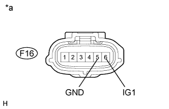
Text in Illustration *a Front view of wire harness connector
(to Compressor with Motor Assembly)
Disconnect the compressor with motor assembly connector.
-
Measure the resistance according to the value(s) in the table below.
Standard Resistance Tester Connection Condition Specified Condition F16-5 (GND) - Body ground Always Below 1 Ω -
Measure the voltage according to the value(s) in the table below.
Standard Voltage Tester Connection Switch Condition Specified Condition F16-6 (IG1) - F16-5 (GND) Power switch on (IG) 11 to 14 V F16-6 (IG1) - F16-5 (GND) Power switch off Below 1 V
NG
REPAIR OR REPLACE HARNESS OR CONNECTOR
OK
-
-
CHECK HARNESS AND CONNECTOR (POWER MANAGEMENT CONTROL ECU - COMPRESSOR WITH MOTOR)
-
Disconnect the A36 power management control ECU connector.
-
Measure the resistance according to the value(s) in the table below.
Standard Resistance Tester Connection Condition Specified Condition F16-1 (CLK) - A36-16 (CLK) Always Below 1 Ω F16-2 (DIN) - A36-17 (ITE) Always Below 1 Ω F16-3 (DOUT) - A36-18 (ETI) Always Below 1 Ω F16-1 (CLK) - Body ground Always 10 kΩ or higher F16-2 (DIN) - Body ground Always 10 kΩ or higher F16-3 (DOUT) - Body ground Always 10 kΩ or higher
NG
REPAIR OR REPLACE HARNESS OR CONNECTOR
OK
-
-
CHECK HIGH VOLTAGE FUSE
CAUTION:
Be sure to wear insulated gloves.
-
Check that the service plug grip is not installed Click here.
Note
After removing the service plug grip, do not turn the power switch on (Ready), unless instructed by the repair manual because this may cause a malfunction.
-
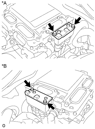
Text in Illustration *A for LHD *B for RHD Remove the connector cover assembly from the inverter with converter assembly Click here.
Tech Tips
Make sure that no foreign objects have entered or contaminated the inverter with converter assembly.
-
Disconnect the connector of the air conditioning harness from the inverter with converter assembly.
-
for LHD
Tech Tips
Make sure that no foreign objects have entered or contaminated the connector of the air conditioning harness.
-
for RHD

Tech Tips
Make sure that no foreign objects have entered or contaminated the connector of the air conditioning harness.
-
-
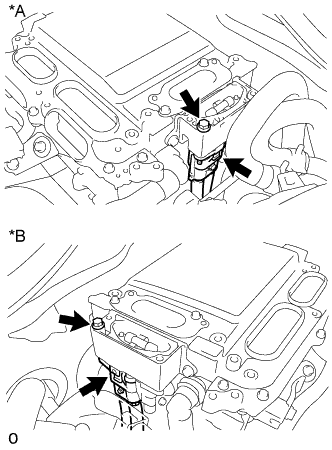
Text in Illustration *A for LHD *B for RHD Disconnect the connector of the No. 4 floor wire from the inverter with converter assembly.
Tech Tips
Make sure that no foreign objects have entered or contaminated the connector of the No. 4 floor wire.
-
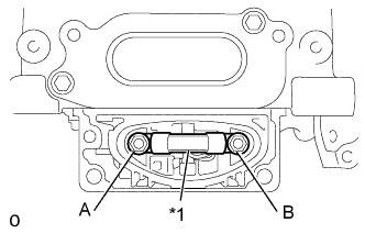
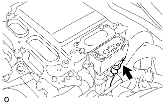
Check that bolts A and B are tightened securely.
-
Measure the resistance according to the value(s) in the table below.
Standard Resistance Tester Item
(Tester Connection)
Condition Specified Condition High voltage fuse
(A - B)
Always Below 1 Ω Text in Illustration *1 High Voltage Fuse
NG
REPLACE HIGH VOLTAGE FUSE Click here
OK
-
-
CHECK AIR CONDITIONING HARNESS
CAUTION:
Be sure to wear insulated gloves.
-
Check that the service plug grip is not installed Click here.
Note
After removing the service plug grip, do not turn the power switch on (Ready), unless instructed by the repair manual because this may cause a malfunction.
-
Remove the air conditioning harness Click here.
Tech Tips
Make sure that no foreign objects have entered or contaminated the inverter with converter assembly.
-
Measure the resistance according to the value(s) in the table below.
Standard Resistance for LHD Tester Connection Condition Specified Condition V1-1 (PE) - V3-1 (ACPE) Always Below 1 Ω V1-2 (PB) - V3-2 (ACPB) Always Below 1 Ω V1-1 (PE) - Body ground Always 10 kΩ or higher V1-2 (PB) - Body ground Always 10 kΩ or higher V-1 (PE) - V1-2 (PB) Always 10 kΩ or higher for RHD Tester Connection Condition Specified Condition f2-1 (PE) - f1-1 (ACPE) Always Below 1 Ω f2-2 (PB) - f1-2 (ACPB) Always Below 1 Ω f2-1 (PE) - Body ground Always 10 kΩ or higher f2-2 (PB) - Body ground Always 10 kΩ or higher f2-1 (PE) - f2-2 (PB) Always 10 kΩ or higher
NG
REPLACE AIR CONDITIONING HARNESS Click here
OK
-
-
CHECK COMPRESSOR WITH MOTOR ASSEMBLY
-
Replace the compressor with motor assembly with a new or normally functioning one Click here.
-
Clear the DTCs Click here.
-
Check for the DTCs Click here.
OK DTC B1498/98 is not output.
NG
REPLACE POWER MANAGEMENT CONTROL ECU Click here
OK 
END (COMPRESSOR WITH MOTOR ASSEMBLY WAS DEFECTIVE)
-