ENGINE UNIT INSTALLATION

-
INSTALL ENGINE COVER
-
Install the engine cover with the 2 clips.
-
-
INSTALL ENGINE COOLANT TEMPERATURE SENSOR
-
Install a new gasket to the engine coolant temperature sensor.
-
Install the engine coolant temperature sensor.
- Torque:
- 20 N*m { 200 kgf*cm, 14 ft.*lbf }
Tech Tips
Perform "Inspection After Repairs" after replacing the engine coolant temperature sensor Click here.
-
-
INSTALL ENGINE OIL PRESSURE SWITCH ASSEMBLY
-
Apply adhesive to 2 or 3 threads of the engine oil pressure switch.
Adhesive Toyota Genuine Adhesive 1324, Three Bond 1324 or equivalent Note
Do not apply adhesive to the oil inlet port of the engine oil pressure switch.
-
Using a 24 mm deep socket wrench, install the engine oil pressure switch.
- Torque:
- 15 N*m { 153 kgf*cm, 11 ft.*lbf }
Note
Do not start the engine for at least 1 hour after installation.
-
Connect the engine oil pressure switch connector.
-
-
INSTALL ENGINE OIL LEVEL SENSOR
-
Install a new gasket to the engine oil level sensor.
-
Install the engine oil level sensor with the 4 bolts.
- Torque:
- 7.0 N*m { 71 kgf*cm, 62 in.*lbf }
Tech Tips
Be sure to clean the contact surface.
-
Connect the engine oil level sensor connector.
-
-
INSTALL IGNITION COIL ASSEMBLY
Tech Tips
Perform "Inspection After Repairs" after replacing the ignition coil Click here.
-
for Bank 1:
-
Install the 3 ignition coils with the 3 bolts.
- Torque:
- 10 N*m { 102 kgf*cm, 7 ft.*lbf }
Tech Tips
Perform "Inspection After Repairs" after replacing the ignition coil Click here.
-
Connect the VVT sensor connector and 3 ignition coil connectors to connect the engine wire.
-
Connect the clamp and install the 2 nuts.
- Torque:
- 10 N*m { 102 kgf*cm, 7 ft.*lbf }
-
-
for Bank 2:
-
Install the 3 ignition coils with the 3 bolts.
- Torque:
- 10 N*m { 102 kgf*cm, 7 ft.*lbf }
Tech Tips
Perform "Inspection After Repairs" after replacing the ignition coil Click here.
-
Connect the manifold absolute pressure sensor connector, VVT sensor connector and 3 ignition coil connectors to connect the engine wire.
-
Connect the 2 clamps and install the 3 nuts.
- Torque:
- 10 N*m { 102 kgf*cm, 7 ft.*lbf }
-
-
Connect the inverter reservoir tank assembly with the 2 bolts.
- Torque:
- 13 N*m { 133 kgf*cm, 10 ft.*lbf }
-
for RHD:
Install the inverter bracket to the inverter with the 2 bolts.
- Torque:
- 8.0 N*m { 82 kgf*cm, 71 in.*lbf }
-
for RHD:
Attach the 2 wire harness clamps to the inverter bracket.
-
-
INSTALL V-BANK COVER BOLT
-
Install the V-bank cover bolt.
- Torque:
- 10 N*m { 102 kgf*cm, 7 ft.*lbf }
-
-
INSTALL V-BANK COVER BRACKET SUB-ASSEMBLY
-
Install the V-bank cover bracket with the bolt.
- Torque:
- 10 N*m { 102 kgf*cm, 7 ft.*lbf }
-
-
INSTALL FUEL INJECTOR SEAL
-
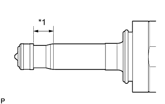
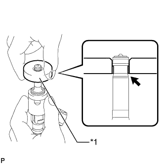
Text in Illustration *1 Clean Area Apply engine conditioner to the injector area shown in the illustration. Using a piece of cloth, clean carbon deposits from the injector and its grooves.
Note
-
Do not clean the tip of the injector.
-
Do not use a wire brush to clean the injector.
-
If an injector is dropped or the tips of the injectors are struck, replace it with a new one.
-
-
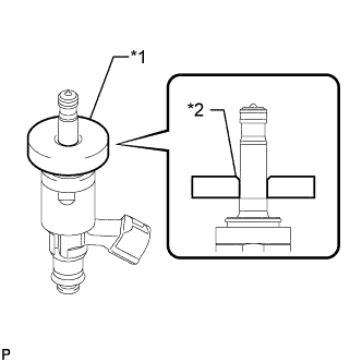
Text in Illustration *1 SST (Guide) *2 Tapered Inner Portion Apply engine oil to the injector contact surface of SST (guide). Then attach SST (guide) to the injector with the tapered inner portion facing the tip of the injector as shown in the illustration.
- SST
- 09260-39020 ( 09261-03020 )
-
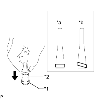
Text in Illustration *1 Fuel Injector Seal *2 SST (Holder) *a CORRECT *b INCORRECT Install a new injector seal to SST (holder).
- SST
- 09260-39020 ( 09261-03010 )
Note
Be careful not to install the injector seal to SST (holder) at an angle. Doing so will stretch the seal and correcting this problem is very complicated.
-
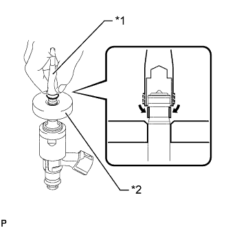
Text in Illustration *1 SST (Holder) *2 SST (Guide) Install SST (holder with injector seal) to the tip of the injector. Slide the seal downward into the injector groove (injector connector side) with your fingers as shown in the illustration.
- SST
- 09260-39020 ( 09261-03010, 09261-03020 )
Tech Tips
Check that the seal covers the circumference of the injector groove as shown in the illustration.
-
Text in Illustration *1 SST (Guide) Slowly slide SST (guide) toward the tip of the injector. When the injector contact surface of SST (guide) aligns with the seal (injector tip side) as shown in the illustration, hold the position for 5 seconds or more to fully align the seal into the injector groove.
- SST
- 09260-39020 ( 09261-03020 )
Note
Be careful that the seal is not pinched between SST (guide) and the injector groove. Replace the seal if it becomes damaged.
Tech Tips
-
Set SST (guide) so that its bottom surface and the seal are flush.
-
If there is difficulty in sliding SST upward, slowly wiggle it from side to side while sliding it up the injector little by little.
-
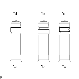
Text in Illustration *a Normal *b Protruding *c Deformed *d CORRECT *e INCORRECT After installing the seals, check that they are not scratched, deformed or protruding from the injector groove.
Note
If a seal is scratched, deformed or protruding from the groove, replace it with a new one.
-
-
INSTALL FUEL INJECTOR ASSEMBLY
Tech Tips
Perform "Inspection After Repairs" after replacing the fuel injector Click here.
-
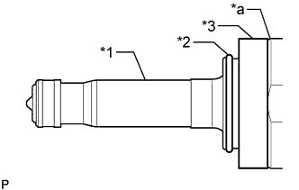
Text in Illustration *1 Injector Assembly *2 C-ring *3 Injector Vibration Insulator *a Tapered Side Install a new injector vibration insulator and a new C-ring to the injector assembly.
Note
-
Install the injector vibration insulator aligning it with the tapered side of the injector assembly.
-
Check that the C-ring is securely fit into the groove of the injector assembly.
-
-
Install a new No. 1 fuel injector back-up ring and a new O-ring as shown in the illustration.
Text in Illustration *1 No. 1 Fuel Injector Back-up Ring *2 O-ring *3 No. 3 Fuel Injector Back-up Ring - - *a No. 1 Fuel Injector Back-up Ring Opening *b Overlapping *c Gap *d OK *e NG - - Note
-
Check that there is no foreign matter or damage in the groove of the O-ring.
-
Do not mistake the direction of the No. 1 fuel injector back-up ring.
-
Do not install the No. 1 fuel injector back-up ring and O-ring in the wrong order.
-
Do not allow the opening of the No. 1 fuel injector back-up ring to separate or overlap as shown in the illustration.
-
-

Text in Illustration *1 Fuel injector assembly *2 No. 3 Fuel Injector Back-up Ring *a Cutout Set a new No. 3 fuel injector back-up ring so that it is level as shown in the illustration, push in the injector assembly and install the No. 3 fuel injector back-up ring.
Note
-
Make sure that the No. 3 fuel injector back-up ring is oriented correctly.
-
After installing the O-ring, make sure there is no damage or foreign matter.
-
-
Install the nozzle holder clamp to the injector.
-
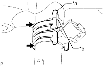
Text in Illustration *a Protrusion *b Positioning Hole 
No gap 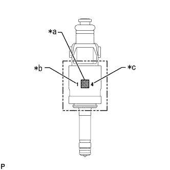
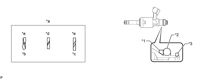
Text in Illustration *a QR Code *b Flow Classification Number *c Oil Seal Classification Number Align the protrusion of the nozzle holder clamp with the positioning hole of the fuel delivery pipe and insert the injector.
Note
-
Install 3 injectors with the same flow classification number (the number to the left of the QR code which is 1, 2 or 3) on each bank (6 injectors with the same flow classification number is also okay).
-
Install an injector with an oil seal classification number (the number to the right of the QR code) of either 4 or 5.
-
Make sure that there is no foreign matter or damage inside the injector insertion holes (fuel delivery pipe).
-
Do not get gasoline on the O-rings or inside the installation holes.
-
If the injector is difficult to insert, apply new engine oil to the chamfered part of the injector insertion hole of the fuel delivery pipe. Also, be careful as it is easier for the injector to fall out of the fuel delivery pipe in this case.
-
Keep the injector straight and do not tilt it when inserting it into the fuel delivery pipe.
-
Check that there is no gap between the fuel delivery pipe and the nozzle holder clamp.
-
-
-
INSTALL FUEL DELIVERY PIPE RH
-
Apply lubricant to the installation hole of the injector.
-
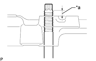
Text in Illustration *a Nut can be attached Insert the stud bolt into the fuel delivery pipe until the screw threads protrude enough so that a nut can be attached.
Note
-
If an injector is dropped or the tips of the injectors are struck, replace it with a new one.
-
Check that there is no foreign matter or damage to the injector insertion hole of the delivery pipe.
-
When inserting the fuel delivery pipe, push it in evenly without tilting it.
-
-
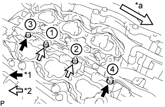
Text in Illustration *1 Bolt *2 Nut *a Front Install the fuel delivery pipe RH by uniformly tightening the 2 bolts and 2 nuts in several passes in the order shown in the illustration.
- Torque:
- 32 N*m { 326 kgf*cm, 24 ft.*lbf }
-
Install the bolt and attach the wire harness clamp.
- Torque:
- 10 N*m { 102 kgf*cm, 7 ft.*lbf }
-
Connect the fuel pressure sensor connector.
Note
Do not pull the wire harness of the fuel pressure sensor excessively.
-
-
INSTALL FUEL DELIVERY PIPE LH
-
Apply lubricant to the installation holes of the injectors.
-
Text in Illustration *a Nut can be attached Insert the stud bolt into the delivery pipe until the screw threads protrude enough so that a nut can be attached.
Note
-
If an injector is dropped or the tips of the injectors are struck, replace it with a new one.
-
Check that there is no foreign matter or damage to the injector insertion hole of the delivery pipe.
-
When inserting the fuel delivery pipe, push it in evenly without tilting it.
-
-
Text in Illustration *1 Bolt *2 Nut *a Front Install the fuel delivery pipe LH by uniformly tightening the 2 bolts and 2 nuts in several passes in the order shown in the illustration.
- Torque:
- 32 N*m { 326 kgf*cm, 24 ft.*lbf }
-
Install the bolt and attach the 2 wire harness clamps.
- Torque:
- 10 N*m { 102 kgf*cm, 7 ft.*lbf }
-
-
INSTALL NO. 2 FUEL PIPE SUB-ASSEMBLY
-
Temporarily install the 2 union nuts of the fuel delivery pipe to the No. 2 fuel pipe sub-assembly until they are completely fastened.
-
Use a 17 mm union nut wrench, tighten the 2 union nuts of the No. 2 fuel pipe sub-assembly.
- Torque:
- 35 N*m { 357 kgf*cm, 26 ft.*lbf }
Note
-
If the 2 union nuts cannot be fastened, loosen the nuts of the fuel delivery pipe RH and fuel delivery pipe LH, and then fasten both union nuts.
-
When a torque wrench is combined with a union nut wrench and used to tighten parts, if the reading from the torque wrench reaches the torque specification, the actual torque will be excessive due to the increase in the total length of the wrench Click here.
-
Do not adjust the torque in the loosening direction.
-
The No. 2 fuel pipe sub-assembly can be reused 10 times.
Tech Tips
-
This torque value is effective when the union nut wrench is parallel to the torque wrench.
-
Install the union nut wrench parallel with the torque wrench.
-
-
SET FUEL PUMP ASSEMBLY
-
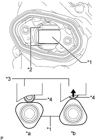
Text in Illustration *1 Camshaft *2 Oil Collection Area *3 Fuel Pump lifter guide *4 Fuel Pump lifter assembly *a OK *b NG Turn the crankshaft so that the flat surface of the camshaft is facing upward from the fuel pump assembly hole of the cylinder head cover.
Tech Tips
By performing the above procedure, the protruding part of the camshaft does not push up the drive face of the pump when installing the fuel pump assembly, thus making installation of the fuel pump and No. 2 fuel pipe sub-assembly easier.
-
Fill the cylinder head oil collection areas with 30 cc (1.8 cu.in.) of engine oil from the fuel pump assembly hole of the cylinder head cover.
-
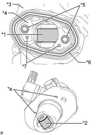
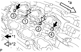
Text in Illustration *1 Pump Drive Cam (Engine Oil Application Point) *2 Pump Lifter (Engine Oil Application Point) *3 Cylinder head cover *4 Pump Housing *5 O-ring *6 Fuel Pump Spacer Gasket *7 Knock Pin *a Positioning Knock Hole Apply engine oil to the pump drive cam and pump lifter.
-
Install 2 new O-rings to the pump housing.
-
Install a new fuel pump spacer gasket to the head cover.
-
Install a new O-ring to the fuel pump.
-
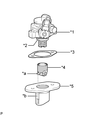
Text in Illustration *1 Fuel Pump *2 O-ring *3 Fuel Pump Insulator *4 Fuel Pump Lifter Assembly *5 Fuel Pump Lifter Guide *a Stopper Key *b Key Groove 
Engine Oil Application Point Apply engine oil to the inside of the fuel pump lifter guide and the outside of the fuel pump lifter assembly.
-
Set the cylinder head cover on the fuel pump assembly as shown in the illustration.
Note
-
Align the stopper key of the fuel pump lifter assembly with the key groove of the fuel pump lifter guide.
-
Align the positioning knock pin of the pump housing with the positioning knock hole of the fuel pump lifter guide.
-
Make sure not to hit the pump lifter part of the fuel pump filter assembly when installing.
-
-
Temporarily install the fuel pump assembly with the 2 bolts, leaving some allowance for left and right movement.
-
-
TEMPORARILY INSTALL NO. 1 FUEL PIPE SUB-ASSEMBLY
-
Temporarily install the union nuts on the fuel delivery pipe side of the No. 1 fuel pipe sub-assembly until they are completely tightened.
-
Temporarily install the union nuts on the fuel pump assembly side of the No. 1 fuel pipe sub-assembly until they are completely tightened.
Note
Do not damage the seals of the union nuts of the No. 1 fuel pipe sub-assembly when installing.
-
-
INSTALL FUEL PUMP ASSEMBLY
Tech Tips
Perform "Inspection After Repairs" after replacing the fuel pump assembly Click here.
-
Uniformly tighten the 2 bolts in several steps to secure the fuel pump assembly to the cylinder head cover.
- Torque:
- 30 N*m { 306 kgf*cm, 22 ft.*lbf }
-
Connect the connector to the fuel pump assembly.
-
-
INSTALL NO. 1 FUEL PIPE SUB-ASSEMBLY
-
Using a 17 mm union nut wrench, tighten the union nuts on the fuel delivery pipe side of the No. 1 fuel pipe sub-assembly.
- Torque:
- 35 N*m { 357 kgf*cm, 26 ft.*lbf }
Note
-
When a torque wrench is combined with a union nut wrench and used to tighten parts, if the reading from the torque wrench reaches the torque specification, the actual torque will be excessive due to the increase in the total length of the wrench Click here.
-
Do not adjust the torque in the loosening direction.
-
The No. 1 fuel pipe sub-assembly can be reused 10 times.
Tech Tips
-
This torque value is effective when the union nut wrench is parallel to the torque wrench.
-
Install the union nut wrench parallel with the torque wrench.
-
Using a 17 mm union nut wrench, tighten the union nuts on the fuel pump assembly side of the No. 1 fuel pipe sub-assembly.
- Torque:
- 35 N*m { 357 kgf*cm, 26 ft.*lbf }
Note
-
When a torque wrench is combined with a union nut wrench and used to tighten parts, if the reading from the torque wrench reaches the torque specification, the actual torque will be excessive due to the increase in the total length of the wrench Click here.
-
Do not adjust the torque in the loosening direction.
-
The No. 1 fuel pipe sub-assembly can be reused 10 times.
Tech Tips
-
This torque value is effective when the union nut wrench is parallel to the torque wrench.
-
Install the union nut wrench parallel with the torque wrench.
-
-
INSTALL NO. 3 WATER BY-PASS PIPE
-
Connect the 2 hoses, and install the bolt and No. 3 water by-pass pipe.
- Torque:
- 10 N*m { 102 kgf*cm, 7 ft.*lbf }
-
-
INSTALL INTAKE MANIFOLD
-
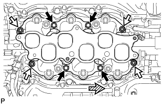
Install 2 new gaskets and the intake manifold with the 4 bolts and 4 nuts.
- Torque:
- 21 N*m { 214 kgf*cm, 15 ft.*lbf }
Text in Illustration Bolt 
Nut 
Front -
Install the fuel tube Click here.
-
Apply engine oil to the threads of the union bolt.
-
Install a new gasket to the fuel tube, and then connect the fuel tube to the fuel pump with the union bolt.
- Torque:
- 23 N*m { 235 kgf*cm, 17 ft.*lbf }
-
Attach the connector to the intake manifold.
-
-
INSTALL NO. 2 SURGE TANK STAY
-
Install the No. 2 surge tank stay with the bolt.
- Torque:
- 21 N*m { 214 kgf*cm, 15 ft.*lbf }
-
-
INSTALL INTAKE AIR SURGE TANK ASSEMBLY
Note
Do not apply oil to the bolts for the parts listed below:
Part Intake air surge tank assembly and intake manifold No. 2 surge tank stay and intake air surge tank assembly
-
Connect the water by-pass hose clamp.
-
Install a new gasket to the intake air surge tank assembly.
-
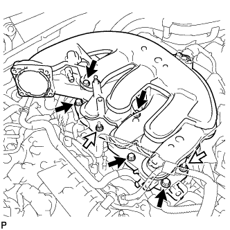
Install the intake air surge tank assembly with the 2 nuts and 5 bolts.
- Torque:
- 21 N*m { 214 kgf*cm, 15 ft.*lbf }
Text in Illustration Bolt Nut -
Install the No. 2 surge tank stay with the bolt.
- Torque:
- 21 N*m { 214 kgf*cm, 15 ft.*lbf }
-
Install the No. 3 water by-pass pipe with the bolt.
- Torque:
- 10 N*m { 102 kgf*cm, 7 ft.*lbf }
-
Connect the No. 2 water by-pass hose to the intake air surge tank assembly.
-
Connect the PCV hose.
-
Connect the connector.
-
Connect the 3 wire harness clamps.
-
Attach the 2 wire harness clamps.
-
Install the nut.
- Torque:
- 10 N*m { 102 kgf*cm, 7 ft.*lbf }
-
-
INSTALL THROTTLE BODY WITH MOTOR ASSEMBLY
-
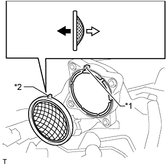
Text in Illustration *1 Groove *2 Protrusion Throttle Body Side Intake Air Surge Tank Side Install a new gasket to the intake air surge tank.
Tech Tips
Align the protrusion of the gasket on the intake air surge tank.
-
Connect the 2 water by-pass hoses to the throttle body.
-
Install the throttle body with the 4 bolts.
- Torque:
- 10 N*m { 102 kgf*cm, 7 ft.*lbf }
Tech Tips
Perform "Inspection After Repairs" after replacing the throttle body with motor Click here.
-
Connect the throttle body with motor connector.
-
-
INSTALL INJECTOR DRIVER
Note
-
Be careful not to drop or strike the injector driver.
-
The injector driver is grounded at the bolt and nut. To make sure that it is grounded, clean all oil and foreign matter from the installation areas of the injector driver and engine before installing the injector driver.
-
Install the injector driver with the bolt and 2 nuts.
- Torque:
- 10 N*m { 102 kgf*cm, 7 ft.*lbf }
-
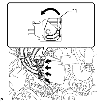
Text in Illustration *1 Lock Lever Connect the 4 connectors to the injector driver. Move the lock levers in the direction indicated by the arrow to lock the 3 connectors.
-
-
INSTALL ENGINE WIRE
-
INSTALL WATER PUMP PULLEY
-
Temporarily install the pulley with the 4 bolts.
-
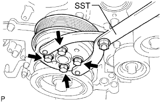
Using SST, hold the pulley and tighten the 4 bolts.
- SST
- 09960-10010 ( 09962-01000, 09963-00700 )
- Torque:
- 21 N*m { 214 kgf*cm, 15 ft.*lbf }
-
-
INSTALL V-RIBBED BELT TENSIONER ASSEMBLY
-
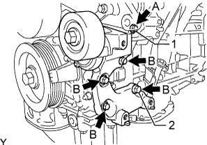
Temporarily install the V-ribbed belt tensioner with the 5 bolts.
Standard Bolt Item Length A 70 mm (2.76 in.) B 35 mm (1.38 in.) -
Install the V-ribbed belt tensioner by tightening the bolt 1 and bolt 2 in the order shown in the illustration.
- Torque:
- 43 N*m { 438 kgf*cm, 32 ft.*lbf }
-
Tighten the other bolts.
- Torque:
- 43 N*m { 438 kgf*cm, 32 ft.*lbf }
-
-
INSTALL FRONT NO. 1 ENGINE MOUNTING BRACKET LH
-
Install the front No. 1 engine mounting bracket LH with the 4 bolts.
- Torque:
- 43 N*m { 438 kgf*cm, 32 ft.*lbf }
-
Connect the 2 clamps.
-
-
INSTALL FRONT NO. 1 ENGINE MOUNTING BRACKET RH
-
Install the front No. 1 engine mounting bracket RH with the 4 bolts.
- Torque:
- 43 N*m { 438 kgf*cm, 32 ft.*lbf }
-
-
INSTALL NO. 1 ENGINE COVER
-
Install the No. 1 engine cover with the 3 clips.
-
-
INSTALL NO. 2 ENGINE COVER
-
Install the No. 2 engine cover with the 3 clips.
-
Connect the clamp.
-