ENGINE UNIT REMOVAL

-
REMOVE NO. 2 ENGINE COVER
-
Remove the 3 clips and clamp, and then remove the No. 2 engine cover.
-
-
REMOVE NO. 1 ENGINE COVER
-
Remove the 3 clips and No. 1 engine cover.
-
-
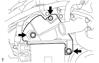
REMOVE FRONT NO. 1 ENGINE MOUNTING BRACKET LH
-
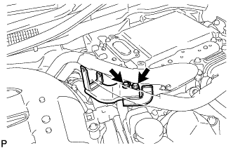
Disconnect the 2 clamps.
-
Remove the 4 bolts and front No. 1 engine mounting bracket LH.
-
-
REMOVE FRONT NO. 1 ENGINE MOUNTING BRACKET RH
-
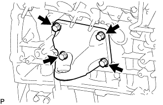
Remove the 4 bolts and front No. 1 engine mounting bracket RH.
-
-
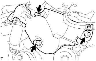
REMOVE V-RIBBED BELT TENSIONER ASSEMBLY
-
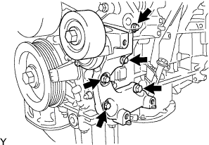
Remove the 5 bolts and V-ribbed belt tensioner.
-
-
REMOVE WATER PUMP PULLEY
-
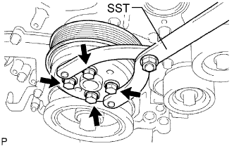
Using SST, hold the water pump pulley.
- SST
- 09960-10010 ( 09962-01000, 09963-00700 )
-
Remove the 4 bolts and water pump pulley.
-
-
REMOVE ENGINE WIRE
-
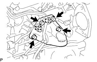
REMOVE INJECTOR DRIVER
-
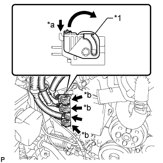
Text in Illustration *1 Lock Lever *a Release *b Lock with Connector Move the lock levers in the direction indicated by the arrow to release the 3 connector locks. Disconnect the 4 connectors from the injector driver.
-
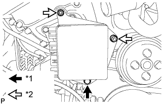
Text in Illustration *1 Bolt *2 Nut Remove the bolt, 2 nuts and injector driver.
Note
Be careful not to drop or strike the injector driver.
-
-
REMOVE THROTTLE BODY WITH MOTOR ASSEMBLY
-
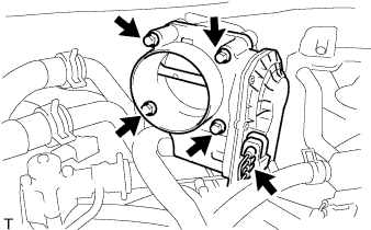
Disconnect the throttle motor connector.
-
Remove the 4 bolts and disconnect the throttle body with motor assembly from the intake air surge tank.
-
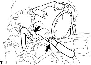
Disconnect the 2 water by-pass hoses from the throttle body with motor assembly.
-
Remove the throttle body with motor assembly and gasket.
-
-
REMOVE INTAKE AIR SURGE TANK ASSEMBLY
-
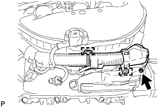
Remove the nut.
-
Detach the 2 clamps and disconnect the wire harness.
-
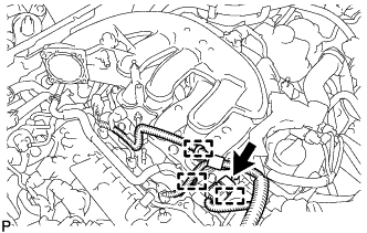
Disconnect the 3 wire harness clamps.
-
Disconnect the connector.
-
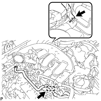
Disconnect the PCV hose.
-
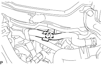
Disconnect the No. 2 water by-pass hose from the intake air surge tank assembly.
-
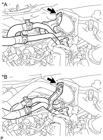
Text in Illustration *A for RHD *B for LHD Remove the bolt and No. 3 water by-pass pipe.
-
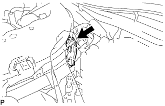
Remove the bolt and separate the No. 2 surge tank stay from the intake air surge tank assembly.
-
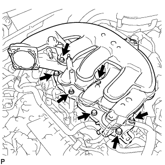
Remove the 2 nuts and 5 bolts from the intake air surge tank assembly.
-
Disconnect the water by-pass hose clamp and remove the intake air surge tank assembly and gasket.
-
-
REMOVE NO. 2 SURGE TANK STAY
-
Remove the bolt and No. 2 surge tank stay.
-
-
REMOVE NO. 3 WATER BY-PASS PIPE
-
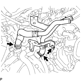
Remove the bolt, and disconnect the 2 hoses and No. 3 water by-pass pipe.
-
-
REMOVE INTAKE MANIFOLD
-
Detach the connector from the intake manifold.
Text in Illustration 
Front -
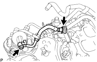
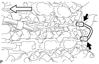
Remove the union bolt, and then disconnect the fuel tube from the fuel pump.
-
Remove the gasket from the fuel tube.
-
Remove the fuel tube Click here.
-
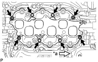
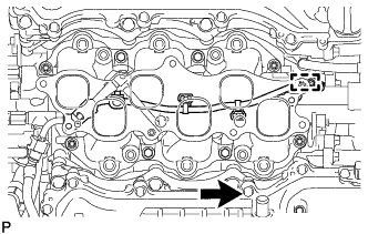
Text in Illustration *a Front Remove the 4 bolts, 4 nuts, intake manifold and 2 gaskets.
-
-
REMOVE NO. 1 FUEL PIPE SUB-ASSEMBLY
-
Loosen the 2 union nuts of the No. 1 fuel pipe sub-assembly.
-
Loosen the 2 bolts of the fuel pump assembly.
-
Remove the No. 1 fuel pipe sub-assembly.
-
-
REMOVE FUEL PUMP ASSEMBLY
-
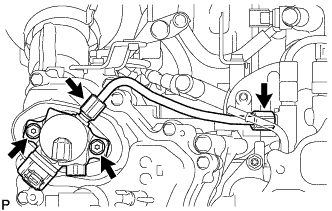
Disconnect the connector from the fuel pump assembly.
-
Remove the 2 bolts and fuel pump assembly.
-
Remove the fuel pump, fuel pump lifter assembly and fuel pump insulator from the fuel pump lifter guide.
-
Remove the O-ring from the fuel pump.
-
Remove the fuel pump spacer gasket from the head cover.
-
Remove the 2 O-rings from the pump housing.
-
-
REMOVE NO. 2 FUEL PIPE SUB-ASSEMBLY
-
Loosen the 2 union nuts and remove the No. 2 fuel pipe sub-assembly from the fuel delivery pipe.
Text in Illustration 
Front
-
-
REMOVE FUEL DELIVERY PIPE LH
-

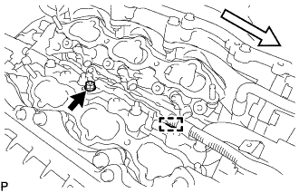
Remove the bolt and detach the 2 wire harness clamps.
Text in Illustration Front -
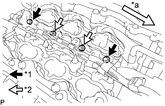
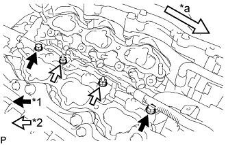
Text in Illustration *1 Bolt *2 Nut *a Front Remove the 2 bolts and 2 nuts.
-
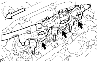
With the connectors still connected, disconnect the fuel delivery pipe LH.
Text in Illustration Front Note
-
Make sure that the fuel delivery pipe is disconnected from the delivery pipe (LH side).
-
Be extremely careful not to touch or strike the tips of the injectors.
-
Pull and remove the fuel pipe in a straight line without tilting it.
-
-
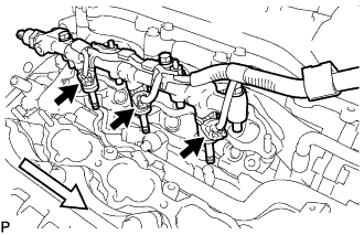
Disconnect the 3 injector connectors.
-
-
REMOVE FUEL DELIVERY PIPE RH
-
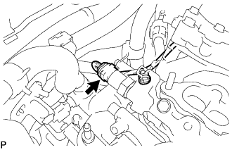
Disconnect the fuel pressure sensor connector.
Note
Do not pull the wire harness of the fuel pressure sensor excessively.
-
Remove the bolt and detach the wire harness clamp.
Text in Illustration Front -
Text in Illustration *1 Bolt *2 Nut *a Front Remove the 2 bolts and 2 nuts.
-
With the connectors still connected, disconnect the fuel delivery pipe RH.
Text in Illustration Front Note
-
Be extremely careful not to touch or strike the tips of the injectors.
-
Pull and remove the fuel pipe in a straight line without tilting it.
-
-
Disconnect the 3 injector connectors.
-
-
REMOVE FUEL INJECTOR ASSEMBLY
-
Fix the fuel delivery pipe in a vise between aluminum plates.
Note
-
Do not tighten the vise more than necessary.
-
Do not damage the fuel injector assemblies.
-
-
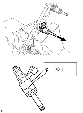
Remove the fuel injector assemblies from the fuel delivery pipe LH and fuel delivery pipe RH.
Note
-
When removing an injector, pull the injector straight out to avoid damaging the O-ring seal surfaces of the fuel delivery pipe LH and fuel delivery pipe RH.
-
After removing the injector, check that the O-ring, No. 1 fuel injector back-up ring and No. 3 fuel injector back-up ring are not remaining on the fuel delivery pipe. If any of the parts remain on the fuel delivery pipe, remove them.
-
Attach a label to the removed injector assembly to distinguish it from other cylinders.
-
-
Remove the nozzle holder clamps from the injectors.
-
Using needle-nose pliers, remove the No. 3 fuel injector back-up ring from the injector assembly.
Note
Do not damage the part contacting the O-ring.
-
Remove the O-ring and No. 1 fuel injector back-up ring.
-
Remove the C-rings and injector vibration insulators from the injectors.
-
-
REMOVE FUEL INJECTOR SEAL
-
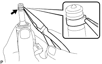
Using the tips of a pair of needle nose pliers, pinch and pull one of the injector seals at several points to stretch it. Repeat this for the other injector seal.
Note
-
Excessively pinching the injector seal may damage the groove of the injector.
-
If an injector is dropped or the tips of the injectors are struck, replace it with a new one.
-
-
Remove the injector seal from the injector.
-
-
REMOVE V-BANK COVER BRACKET SUB-ASSEMBLY
-
Remove the bolt and V-bank cover bracket.
-
-
REMOVE V-BANK COVER BOLT
-
Remove the V-bank cover bolt.
-
-
REMOVE IGNITION COIL ASSEMBLY
-
for RHD:
Detach the 2 wire harness clamps from the inverter bracket.
-
for RHD:
Remove the 2 bolts and inverter bracket from the inverter.
-
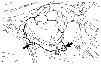
Remove the 2 bolts and disconnect the inverter reservoir tank assembly.
-
for Bank 1:
-
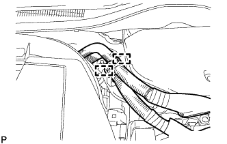
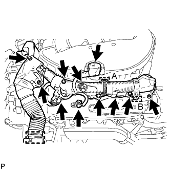
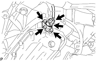
Remove the 3 nuts and disconnect the clamp labeled A using a clip remover. Then, disconnect the clamp labeled B using needle-nose pliers.
Note
Do not damage the claws of the clamp.
-
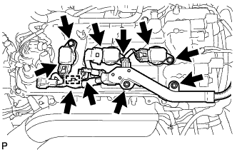
Disconnect the manifold absolute pressure sensor connector, VVT sensor connector and 3 ignition coil connectors to disconnect the engine wire.
-
Remove the 3 bolts and 3 ignition coils.
-
-
for Bank 2:
-
Remove the 2 nuts and disconnect the clamp.
-
Disconnect the VVT sensor connector and 3 ignition coil connectors to disconnect the engine wire.
-
Remove the 3 bolts and 3 ignition coils.
-
-
-
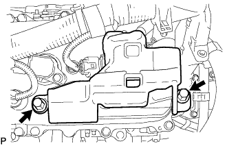
REMOVE ENGINE OIL LEVEL SENSOR
-
Disconnect the engine oil level sensor connector.
-
Remove the 4 bolts and engine oil level sensor.
-
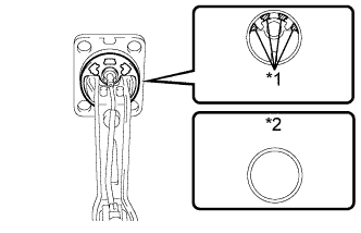
Text in Illustration *1 Cutting Position *2 Supply Part Cut off the gasket as shown in the illustration.
-
Remove the gasket from the engine oil level sensor.
Tech Tips
After cutting away the parts of the gasket shown in the illustration, remove only the outer part of the gasket.
-
-
REMOVE ENGINE OIL PRESSURE SWITCH ASSEMBLY
-
Disconnect the engine oil pressure switch connector.
-
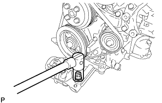
Using a 24 mm deep socket wrench, remove the engine oil pressure switch.
-
-
REMOVE ENGINE COOLANT TEMPERATURE SENSOR
-
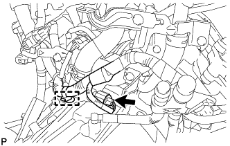
Disconnect the clamp and connector.
-
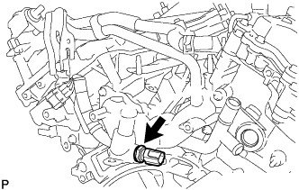
Remove the engine coolant temperature sensor and gasket.
-
-
REMOVE ENGINE COVER
-
Remove the 2 clips and engine cover.
-