ENGINE ASSEMBLY INSTALLATION

CAUTION:
As the engine assembly with transmission is extremely heavy, the engine lifter may suddenly drop if the instructions listed in the repair manual are not followed. Therefore, always follow the instructions listed in the repair manual when performing this procedure.
-
INSTALL REAR NO. 1 ENGINE MOUNTING INSULATOR
Tech Tips
Only perform this procedure when replacement of the engine mounting insulator is necessary.
-
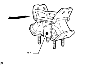
Text in Illustration *1 Paint Mark 
Rear of Vehicle Install the rear No. 1 engine mounting insulator to the hybrid vehicle transmission assembly with the 4 bolts.
- Torque:
- 52 N*m { 530 kgf*cm, 38 ft.*lbf }
Tech Tips
Make sure that the paint mark faces toward the rear of the vehicle.
-
-
INSTALL FRONT ENGINE MOUNTING INSULATOR
Tech Tips
Only perform this procedure when replacement of the engine mounting insulator is necessary.
-
Install the front engine mounting insulator RH and LH with the 2 nuts.
- Torque:
- 70 N*m { 714 kgf*cm, 52 ft.*lbf }
-
-
INSTALL ENGINE HANGER
-
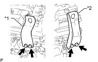
Text in Illustration *1 No. 1 Engine Hanger *2 No. 2 Engine Hanger Install the 2 No. 1 engine hangers with the 4 bolts as shown in the illustration.
- Torque:
- 33 N*m { 337 kgf*cm, 24 ft.*lbf }
Tech Tips
No. 1 engine hanger 12281 - 31130 No. 2 engine hanger 12282 - 31140 Bolt 91671 - F0822
-
-
REMOVE ENGINE STAND
-
Attach an engine sling device and hang the engine with a chain block.
Note
Pay attention to the angle of the sling device as the engine assembly or engine hangers may be damaged or deformed if the angle is incorrect.
-
Lift the engine and remove it from the engine stand.
Note
With the exception of installing the engine assembly to an engine stand or removing the engine assembly from an engine stand, do not perform any work on the engine while it is suspended, as doing so is dangerous.
-
Place the engine onto a work bench.
-
-
INSTALL FRONT SUSPENSION CROSSMEMBER SUB-ASSEMBLY
-
Install the front suspension crossmember sub-assembly with the 2 bolts.
- Torque:
- 35 N*m { 357 kgf*cm, 26 ft.*lbf }
-
-
INSTALL FAN AND GENERATOR V BELT
-
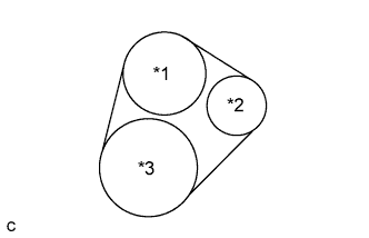
Text in Illustration *1 Engine Water Pump *2 Tensioner *3 Crankshaft Set the fan and generator V belt onto every part.
-
While turning the belt tensioner counterclockwise, remove the 5 mm bi-hexagon wrench.
Note
-
Put the backside of the fan and generator V belt on the tensioner pulley and idler pulley.
-
Check that the fan and generator V belt is properly set to each pulley.
-
-
If it is difficult to install the fan and generator V belt, perform the following procedure.
-
Put the fan and generator V belt on every part except the tensioner pulley.
-
Put the fan and generator V belt on the tensioner pulley while turning the belt tensioner counterclockwise.
Note
-
Put the backside of the fan and generator V belt on the tensioner pulley and idler pulley.
-
Check that the fan and generator V belt is properly set to each pulley.
-
-
-
Check that the belt fits properly in the ribbed grooves.
Tech Tips
Make sure to check by hand that the belt has not slipped out of the grooves on the bottom of the pulley.
-
-
INSTALL COMPRESSOR WITH MOTOR ASSEMBLY
-
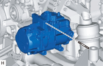
Using an E8 "TORX" socket, install the compressor with motor assembly with the stud bolt.
- Torque:
- 10 N*m { 102 kgf*cm, 7 ft.*lbf }
-
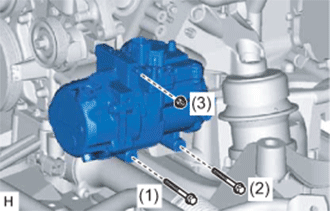
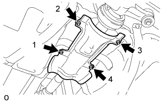
Install the compressor with motor assembly with the 2 bolts and nut.
- Torque:
- 25 N*m { 250 kgf*cm, 18 ft.*lbf }
Note
Tighten the bolts in the order shown in the illustration to install the compressor with motor assembly.
-
-
INSTALL FLYWHEEL SUB-ASSEMBLY
-
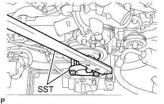
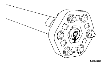
Using SST, hold the crankshaft pulley.
- SST
- 09213-70010 ( 09213-70020 )
- 09330-00021
-
Clean the 8 bolts and 8 bolt holes.
-
Apply a few drops of adhesive to 2 or 3 threads of the 6 bolt tips.
Adhesive Toyota Genuine Adhesive 1324, Three Bond 1324 or equivalent -
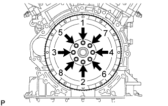
In several steps, uniformly install and tighten the 8 bolts in the sequence shown in the illustration.
- Torque:
- 83 N*m { 846 kgf*cm, 61 ft.*lbf }
-
-
INSTALL TRANSMISSION INPUT DAMPER COVER ASSEMBLY
-
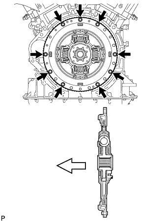
Install the damper cover with the 9 bolts.
- Torque:
- 49 N*m { 504 kgf*cm, 36 ft.*lbf }
Text in Illustration 
Flywheel Side Note
Make sure to insert the damper cover in the correct direction.
-
-
INSTALL HYBRID VEHICLE TRANSMISSION ASSEMBLY
-
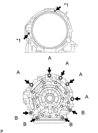
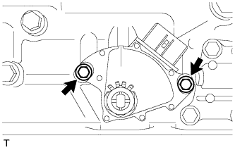
Text in Illustration *1 Knock Pin Make sure that the knock pins are installed on the engine.
-
Install the hybrid vehicle transmission assembly to the engine with the 9 bolts shown in the illustration.
- Torque:
- for Bolt A
- 71 N*m { 724 kgf*cm, 52 ft.*lbf }
- for Bolt B
- 37 N*m { 377 kgf*cm, 27 ft.*lbf }
Note
-
Do not use excessive force to pry on the hybrid vehicle transmission assembly.
-
Do not apply grease either to the splines or input shaft.
Tech Tips
Bolt A: 50 mm (1.97 in.)
Bolt B: 43 mm (1.69 in.)
-
-
INSTALL FLYWHEEL HOUSING SIDE COVER
-
Install the flywheel housing side cover.
-
-
INSTALL STARTER HOLE INSULATOR
-
Install the starter hole insulator with the 2 bolts.
- Torque:
- 58 N*m { 591 kgf*cm, 43 ft.*lbf }
-
-
INSTALL TRANSMISSION BREATHER HOSE SUB-ASSEMBLY
-
Install the transmission breather hose sub-assembly with the clamp.
-
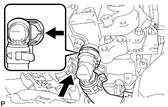
Connect the transmission breather hose sub-assembly to the oil with motor pump assembly, and slide the clamp to secure it.
-
Install the transmission breather hose with the 2 bolts.
- Torque:
- 7.0 N*m { 71 kgf*cm, 62 in.*lbf }
-
Install a new O-ring.
-
Coat the O-ring with ATF.
-
Install the transmission breather plug.
-
-
INSTALL WATER PIPE AND HOSE SUB-ASSEMBLY
-
for RH Side:
-
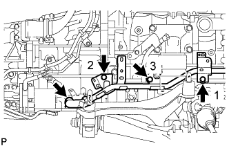
Install the 3 bolts to the water pipe and hose sub-assembly in the order shown in the illustration.
- Torque:
- 22 N*m { 224 kgf*cm, 16 ft.*lbf }
-
Connect the water pipe and hose sub-assembly to the hybrid vehicle transmission assembly, and slide the clip to secure it.
-
-
for LH Side:
-
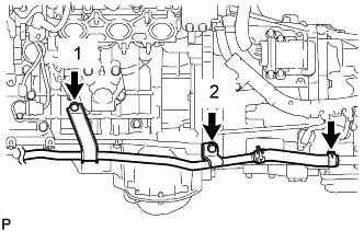
Install the 2 bolts to the water pipe and hose sub-assembly in the order shown in the illustration.
- Torque:
- 22 N*m { 224 kgf*cm, 16 ft.*lbf }
-
Connect the water pipe and hose sub-assembly to the hybrid vehicle transmission assembly, and slide the clip to secure it.
-
-
-
INSTALL OIL COOLER HOSE TUBE SUB-ASSEMBLY
-
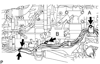
Install the oil cooler hose tube sub-assembly with the 2 bolts.
- Torque:
- for Bolt A
- 12 N*m { 122 kgf*cm, 9 ft.*lbf }
- for Bolt B
- 8.0 N*m { 82 kgf*cm, 71 in.*lbf }
-
Connect the oil cooler hose tube sub-assembly to the oil cooler union sub-assembly, and slide the 2 clips to secure it.
-
-
CONNECT WIRE HARNESS
Note
When installing the motor cable and generator cable, minimize bending of the transmission end of the cable.
-
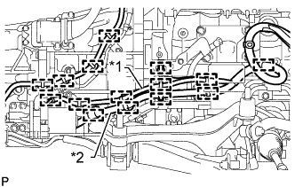
Text in Illustration *1 Signal Line *2 Power Line Connect the 15 wire harness clamps to the hybrid vehicle transmission assembly.
Note
Do not cross or entangle the signal line and power line.
-
Install the wire harness to the hybrid vehicle transmission assembly with the 3 bolts and clamp.
-
for RHD:
Connect the 5 cable clamps.
-
for LHD:
Connect the 6 cable clamps.
-
Install the ground cable with the bolt.
- Torque:
- 10 N*m { 102 kgf*cm, 7 ft.*lbf }
-
-
CONNECT CONNECTOR
-
Connect the shift lever position sensor connector, transmission wire connector, transmission speed sensor connector, engine oil level sensor connector, O/P THERM connector, oil pressure sensor connector, generator revolution connector and motor revolution connector.
Note
Make sure that the wire harness for the oil level sensor is positioned in front of the wire harness of the electrical oil pump.
-
-
INSTALL REAR ENGINE MOUNTING MEMBER
-
Install the engine rear mounting member to the hybrid vehicle transmission assembly with the 4 nuts.
- Torque:
- 13 N*m { 133 kgf*cm, 10 ft.*lbf }
-
-
INSTALL EXHAUST MANIFOLD SUB-ASSEMBLY LH
-
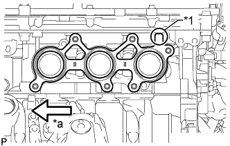
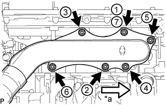
Text in Illustration *1 Protrusion *a Front Install a new gasket as shown in the illustration.
-
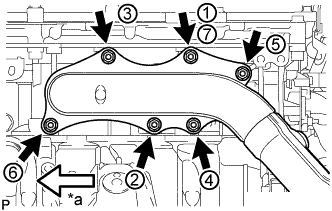
Text in Illustration *a Front Temporarily install the exhaust manifold sub-assembly LH with 6 new nuts.
-
Tighten the 6 nuts in the sequence shown in the illustration.
- Torque:
- 21 N*m { 214 kgf*cm, 15 ft.*lbf }
Note
-
When installing the exhaust manifold, make sure that the flange surface of the exhaust manifold is pressed against the engine and install the nuts in the order shown in the illustration. Make sure to tighten the nut that was tightened first twice at the end.
-
Make sure that the exhaust manifold is correctly fitted onto the stud bolts.
-
Connect the air fuel ratio sensor connector and attach the clamp.
-
-
INSTALL EXHAUST MANIFOLD SUB-ASSEMBLY RH
-
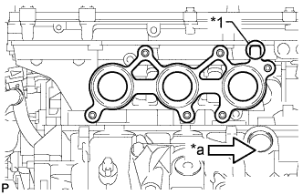
Text in Illustration *1 Protrusion *a Front Install a new gasket as shown in the illustration.
-
Text in Illustration *a Front Temporarily install the exhaust manifold sub-assembly RH with 6 new nuts.
-
Tighten the 6 nuts in the sequence shown in the illustration.
- Torque:
- 21 N*m { 214 kgf*cm, 15 ft.*lbf }
Note
-
When installing the exhaust manifold, make sure that the flange surface of the exhaust manifold is pressed against the engine and install the nuts in the order shown in the illustration. Make sure to tighten the nut that was tightened first twice at the end.
-
Make sure that the exhaust manifold is correctly fitted onto the stud bolts.
-
Connect the air fuel ratio sensor connector and attach the clamp.
-
-
INSTALL ENGINE UNDER COVER SUB-ASSEMBLY LH
-
Install the engine under cover sub-assembly LH.
-
-
INSTALL ENGINE UNDER COVER SUB-ASSEMBLY RH
-
Install the engine under cover sub-assembly RH.
-
-
INSTALL ENGINE OIL LEVEL DIPSTICK GUIDE
-
Install a new O-ring to the engine oil level dipstick guide.
-
Apply a light coat of engine oil to the O-ring.
-
Push in the engine oil level dipstick guide end into the guide hole.
-
Install the engine oil level dipstick guide with the bolt.
- Torque:
- 10 N*m { 102 kgf*cm, 7 ft.*lbf }
-
-
INSTALL NO. 2 ENGINE OIL LEVEL DIPSTICK GUIDE
-
Install a new O-ring to the No. 2 oil level dipstick guide.
-
Install the No. 2 oil level dipstick guide with the bolt.
- Torque:
- 21 N*m { 214 kgf*cm, 15 ft.*lbf }
-
Install the oil level dipstick.
-
-
INSTALL ENGINE AND TRANSMISSION ASSEMBLY
-
Set the engine on an engine lifter.
Note
-
Place wooden blocks or plate lift attachments so that the engine is level.
-
With the exception of installing the engine assembly to an engine stand or removing the engine assembly from an engine stand, do not perform any work on the engine while it is suspended, as doing so is dangerous.
-
Never install attachments to the oil pan of the engine assembly or transmission as doing so may deform the oil pan.
-
-
Remove the 4 bolts and 2 No. 1 engine hangers.
-
Operate the engine lifter and install the engine to the vehicle.
Note
Make sure that the engine is clear of all wiring and hoses.
-
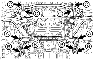
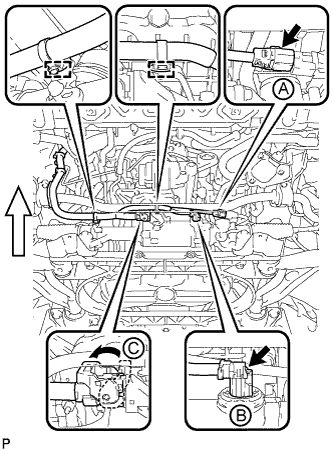
Install the engine and transmission assembly with crossmember with the 6 bolts, 4 new bolts and 2 nuts.
- Torque:
- for bolt A
- 194 N*m { 1978 kgf*cm, 143 ft.*lbf }
- for bolt B
- 50 N*m { 510 kgf*cm, 37 ft.*lbf }
- for bolt C
- 49 N*m { 500 kgf*cm, 36 ft.*lbf }
- for nut
- 151 N*m { 1540 kgf*cm, 111 ft.*lbf }
Text in Illustration Bolt Nut -
Install the rear engine mounting member with the 4 bolts.
- Torque:
- 35 N*m { 354 kgf*cm, 26 ft.*lbf }
-
Connect the wire harness with the nut.
- Torque:
- 5.4 N*m { 55 kgf*cm, 48 in.*lbf }
-
-
INSTALL FRONT LOWER SUSPENSION MEMBER PROTECTOR
-
Install the front lower suspension member protector with the 4 bolts.
- Torque:
- 5.5 N*m { 56 kgf*cm, 49 in.*lbf }
-
-
INSTALL FRONT NO. 2 UPPER SUSPENSION MEMBER
-
Install the 2 front No. 2 upper suspension members with the 6 bolts.
- Torque:
- 20 N*m { 204 kgf*cm, 15 ft.*lbf }
-
-
CONNECT FLOOR SHIFT GEAR SHIFTING ROD SUB-ASSEMBLY
-
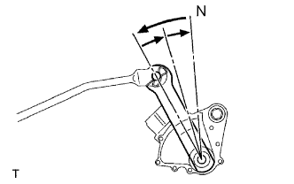
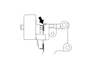
Turn the transmission control shaft lever RH of the park/neutral position switch assembly counterclockwise until it stops, and then turn it clockwise 2 notches to set it to N.
-
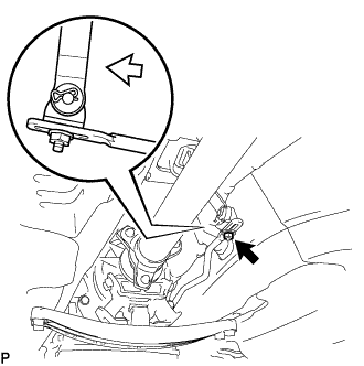
Move the shift lever to N and tighten the nut while lightly pushing the lever toward R.
Text in Illustration Push Note
Do not push the shift lever too hard.
-
After adjustment, check that the shift lever moves smoothly and the shift lever and gear operate correctly.
-
Connect the floor shift gear shifting rod sub-assembly with the nut.
- Torque:
- 13 N*m { 130 kgf*cm, 9 ft.*lbf }
-
-
CONNECT POWER STEERING LINK WIRE HARNESS
-
Connect the wire harness connector (C) to the power steering link assembly and securely lock the connector.
Text in Illustration Front -
Connect the 2 wire harness connectors (A) and (B) to the power steering link assembly.
-
Connect the 2 wire harness clamps to the bracket.
-
-
CONNECT FRONT LOWER BALL JOINT ASSEMBLY LH
-
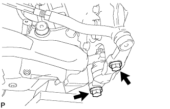
Install the steering knuckle to the lower ball joint with the 2 bolts.
- Torque:
- 150 N*m { 1530 kgf*cm, 111 ft.*lbf }
-
-
CONNECT FRONT LOWER BALL JOINT ASSEMBLY RH
Tech Tips
Install the RH side following the same procedure as for the LH side.
-
CONNECT FRONT SHOCK ABSORBER ASSEMBLY LH
-
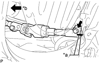
Connect the lower part of the front shock absorber assembly LH to the front lower suspension arm assembly with the bolt and nut.
- Torque:
- 108 N*m { 1101 kgf*cm, 80 ft.*lbf }
Note
-
Insert the bolt from the rear of the vehicle.
-
When tightening the bolt, keep the nut from rotating.
-
-
CONNECT FRONT SHOCK ABSORBER ASSEMBLY RH
Tech Tips
Install the RH side following the same procedure as for the LH side.
-
CONNECT STEERING SLIDING WITH SHAFT YOKE SUB-ASSEMBLY (w/o VGRS)
-
Text in Illustration *a Matchmark *b Vehicle Interior Align the matchmark on the steering sliding with shaft yoke with the matchmark on the power steering link and install the bolt.
- Torque:
- 35 N*m { 360 kgf*cm, 26 ft.*lbf }
-
Tighten the bolt closest to the vehicle interior.
- Torque:
- 35 N*m { 360 kgf*cm, 26 ft.*lbf }
-
-
CONNECT STEERING SLIDING WITH SHAFT YOKE SUB-ASSEMBLY (w/ VGRS)
-
Align the matchmarks and correct the steering sliding with shaft yoke sub-assembly to the power steering gear assembly.
-
Install the 2 bolts.
- Torque:
- 35 N*m { 360 kgf*cm, 26 ft.*lbf }
-
-
INSTALL PROPELLER WITH CENTER BEARING SHAFT ASSEMBLY
-
Apply grease to the flexible coupling centering bushings.
Grease Molybdenum disulphide lithium base NLGI No. 2 -
Completely remove any oil or the like and clean the contact surfaces of the transmission companion flange and flexible coupling.
-
Completely remove any oil or the like and clean the contact surfaces of the differential companion flange and flexible coupling.
-
Align the matchmarks on the transmission companion flange and flexible coupling.
-
Install and tighten the 3 bolts, 3 washers and 3 nuts.
- Torque:
- 79 N*m { 806 kgf*cm, 58 ft.*lbf }
Note
Be careful not to damage the flexible coupling centering bushings.
Tech Tips
The bolts should be installed from the propeller intermediate shaft assembly side.
-
Align the matchmarks on the differential companion flange and flexible coupling.
-
Install and tighten the 3 bolts, 3 washers and 3 nuts.
- Torque:
- 79 N*m { 806 kgf*cm, 58 ft.*lbf }
Note
Be careful not to damage the flexible coupling centering bushings.
Tech Tips
The bolts should be installed from the propeller shaft assembly side.
-
for 2GR-FXE:
Temporarily install the 2 center support bearing dampers with the 2 washers.
Tech Tips
Use the adjusting washers which were removed.
-
for 2AR-FSE:
Temporarily install the 2 bolts with the 2 washers.
Tech Tips
Use the adjusting washers which were removed.
-
-
FULLY TIGHTEN NO. 1 CENTER SUPPORT BEARING ASSEMBLY
-
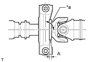
Text in Illustration *a 90° Adjust the distance (A) between the surface of the center support bearing and the surface of the cushion to 11.5 to 13.5 mm (0.453 to 0.531 in.) as shown in illustration.
Distance (A) 11.5 to 13.5 mm (0.453 to 0.531 in.) -
Check that the center line of the bracket is at right angles to the shaft axial direction.
-
for 2GR-FXE:
Tighten the 2 center support bearing dampers.
- Torque:
- 49 N*m { 501 kgf*cm, 36 ft.*lbf }
-
for 2AR-FSE:
Tighten the 2 bolts.
- Torque:
- 49 N*m { 501 kgf*cm, 36 ft.*lbf }
-
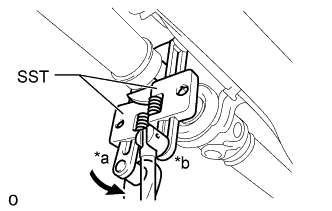
Text in Illustration *a Turn *b Hold Using SST, tighten the adjusting nut.
- SST
- 09922-10010
- Torque:
- without SST
- 69 N*m { 704 kgf*cm, 51 ft.*lbf }
- with SST
- 47 N*m { 479 kgf*cm, 35 ft.*lbf }
Tech Tips
Use a torque wrench with a fulcrum length of 34.5 cm (13.6 in.).
-
-
INSPECT AND ADJUST NO. 2 AND NO. 3 JOINT ANGLE
Note
Measure the joint angle when the vehicle is raised using a four-post lift or when using a pit.
Tech Tips
If any vibration or noise occurs, perform the joint angle check as follows and replace the No. 2 center support bearing washer with a proper one.
-
Stabilize the propeller shaft and differential.
-
Turn the propeller shaft several times by hand to stabilize the center support bearing.
-
Using a jack, raise and lower the differential to stabilize the differential mounting cushion.
-
-
Check the No. 2 and No. 3 joint angles.
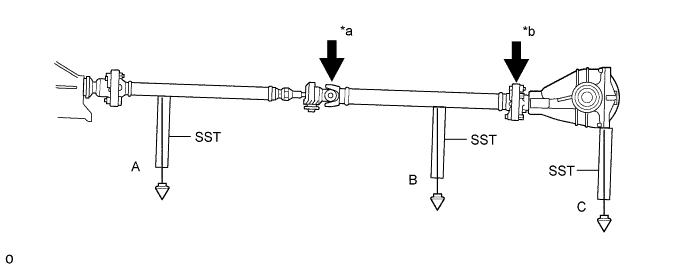
Text in Illustration *a No. 2 Joint Angle *b No. 3 Joint Angle
-
Using SST, measure the installation angle of the propeller intermediate shaft assembly and propeller shaft assembly.
- SST
- 09370-50010
Tech Tips
SST should be set directly underneath the shaft.
-
Using SST, measure the installation angle of the differential.
- SST
- 09370-50010
Tech Tips
Measure the installation angle by placing SST in the positions shown in the illustration.
-
Calculate the No. 2 joint angle.
No. 2 joint angle A - B = -0°30' to 0°30' A Propeller intermediate shaft installation angle B Propeller shaft assembly installation angle -
Calculate the No. 3 joint angle.
No. 3 joint angle B - C = 0°42' to 1°42' B Propeller shaft assembly installation angle C Differential installation angle If the measured angle is not within the specified range, adjust it with the center support bearing washers.
-
-
Adjust the No. 2 joint angle.
-
Select the center support bearing washers for adjustment.
Center Support Bearing Washer Part No. Thickness mm (in.) 90201 - 10106 2.0 (0.0787) 90201 - 10008 4.5 (0.1772) 90201 - 10033 6.5 (0.2559) 90201 - 10017 9.0 (0.3543) 90201 - 10034 11.0 (0.4331) Note
-
Make sure to use a washer of the same thickness on both the right and left sides.
-
Do not use 2 or more washers on a bolt.
-
-
-
-
INSTALL FRONT NO. 1 FLOOR HEAT INSULATOR
-
Install the front No. 1 floor heat insulator with the 4 nuts.
- Torque:
- 5.4 N*m { 55 kgf*cm, 48 in.*lbf }
-
-
INSTALL NO. 1 FUEL TANK PROTECTOR
-
Install the No. 1 fuel tank protector with the 4 nuts and tighten the nuts in the order shown in the illustration.
- Torque:
- 5.0 N*m { 51 kgf*cm, 44 in.*lbf }
-
-
INSTALL FRONT CENTER FLOOR BRACE SUB-ASSEMBLY
-
Install the front center floor brace sub-assembly with the 4 bolts.
- Torque:
- 7.4 N*m { 75 kgf*cm, 65 in.*lbf }
-
-
INSTALL NO. 1 EXHAUST PIPE SUPPORT BRACKET SUB-ASSEMBLY
-
Install the No. 1 exhaust pipe support bracket sub-assembly with the 2 bolts.
- Torque:
- 43 N*m { 438 kgf*cm, 32 ft.*lbf }
-
-
INSTALL FRONT EXHAUST PIPE ASSEMBLY
-
w/ Towing Package:
Tech Tips
Only perform this procedure when replacement of the front No. 1 exhaust pipe protector is necessary.
-
Install the front No. 1 exhaust pipe protector and exhaust pipe protector stay with the 2 bolts and 2 nuts.
- Torque:
- 11 N*m { 107 kgf*cm, 8 ft.*lbf }
-
Install the clamp with the bolt.
- Torque:
- 11 N*m { 107 kgf*cm, 8 ft.*lbf }
-
-
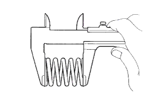
Using a vernier caliper, measure the free length of the compression springs.
Minimum free length 38.5 mm (1.52 in.) Tech Tips
If the free length is less than the minimum, replace the compression spring.
-
Install 2 new gaskets to the front exhaust pipe assembly.
-
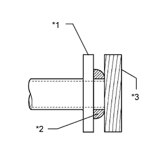
Text in Illustration *1 Front Exhaust Pipe Assembly *2 Gasket *3 Wooden Block Using a plastic-faced hammer and wooden block, tap in a new gasket until its surface is flush with the front exhaust pipe assembly.
Note
-
Be careful with the installation direction of the gasket.
-
Do not reuse the gasket.
-
Do not damage the gasket.
-
Do not push in the gasket by using the exhaust pipe when connecting it.
-
-
Install 2 new gaskets and the front exhaust pipe with 4 new nuts, the 8 bolts, and the 4 compression springs.
- Torque:
- for exhaust manifold side
- 39 N*m { 398 kgf*cm, 29 ft.*lbf }
- for tailpipe side
- 43 N*m { 438 kgf*cm, 32 ft.*lbf }
-
-
CONNECT HEATED OXYGEN SENSOR (for Bank 2 Sensor 2)
-
Connect the heated oxygen sensor connector.
-
-
CONNECT HEATED OXYGEN SENSOR (for Bank 1 Sensor 2)
-
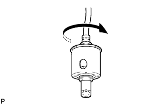
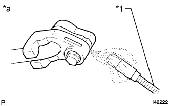
Before installing the heated oxygen sensor, twist the sensor wire counterclockwise 4 turns.
-
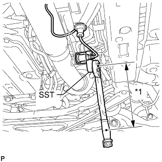
Text in Illustration *1 Fulcrum Length Using SST, connect the heated oxygen sensor to the front exhaust pipe assembly.
- SST
- 09224-00010
- Torque:
- without SST
- 44 N*m { 449 kgf*cm, 32 ft.*lbf }
- with SST
- 40 N*m { 408 kgf*cm, 30 ft.*lbf }
Tech Tips
-
Use a torque wrench with a fulcrum length of 300 mm (11.8 in.). When using a torque wrench with a fulcrum length that is not 300 mm (11.8 in.), calculate the torque specification for the torque wrench and SST based on the "without SST" torque specification Click here.
-
Make sure SST and the wrench are connected in a straight line.
-
After installing the sensor, check that the sensor wire is not twisted.
If the sensor wire is twisted, reinstall the sensor.
-
Connect the grommet of the heated oxygen sensor.
-
-
INSTALL FRONT CENTER FLOOR BRACE
-
Install the front center floor brace and tighten the 2 clips.
-
Install the 6 bolts and 2 nuts.
- Torque:
- 19 N*m { 194 kgf*cm, 14 ft.*lbf }
-
-
INSTALL NO. 2 REAR FLOOR BOARD SUB-ASSEMBLY
-
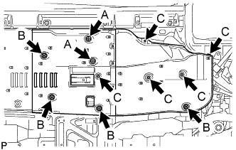
Push in the 2 clips labeled A in the illustration in the upward direction of the vehicle and install the No. 2 rear floor board sub-assembly.
-
Tighten the 4 clips labeled B in the illustration.
-
Install the 5 clips labeled C in the illustration.
-
-
INSTALL NO. 1 REAR FLOOR BOARD SUB-ASSEMBLY
-
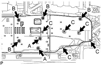
Push in the 2 clips labeled A in the illustration in the upward direction of the vehicle and install the No. 1 rear floor board sub-assembly.
-
Tighten the 4 clips labeled B in the illustration.
-
Install the 5 clips labeled C in the illustration.
-
-
CONNECT ENGINE WIRE
-
Engine Room LH Side:
-
Connect the No. 2 connector holder with the clamp and 3 claws.
-
Connect the 3 connectors from the No. 2 connector holder.
-
Install the No. 1 engine room relay block cover.
-
-
Engine Room RH Side:
-
Install the bolt, clamp and No. 3 engine wire.
- Torque:
- 8.5 N*m { 87 kgf*cm, 75 in.*lbf }
-
-
-
CONNECT INVERTER RESERVOIR TANK ASSEMBLY (for LHD)
-
Install the inverter reservoir tank assembly with the 2 bolts.
- Torque:
- 13 N*m { 133 kgf*cm, 10 ft.*lbf }
-
Connect the No. 3 inverter cooling hose and No. 4 inverter cooling hose.
-
-
CONNECT INVERTER RESERVOIR TANK ASSEMBLY (for RHD)
-
Connect the No. 2 inverter cooling outlet hose to the inverter with converter assembly and lock the hose with the retainer.
Note
-
Insert the retainer until a click sound is heard.
-
Pull on the hose to confirm that the hose is securely connected.
-
If there is foreign matter on the union or the O-ring, clean it with water and finger scouring.
-
To prevent foreign matter from entering the cooling system, do not remove the pieces of cloth or plastic bags from the pipes and disconnected hoses.
-
-
Connect the inverter reservoir tank assembly to the No. 4 inverter cooling hose and install the 2 bolts.
- Torque:
- 13 N*m { 133 kgf*cm, 10 ft.*lbf }
-
-
CONNECT MOTOR CABLE
CAUTION:
Wear insulated gloves.
Note
-
Do not damage the terminals, connector housings or inverter with converter assembly when connecting them.
-
Do not touch the connector waterproofing rubber or terminals.
-
Do not allow any foreign objects or water to enter the inverter with converter assembly.
-
Temporarily install the motor cable with the 5 bolts.
-
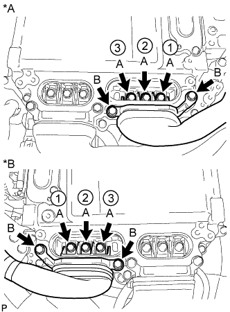
Text in Illustration *A for LHD *B for RHD Using an insulated tool, tighten the 3 bolts labeled A in the illustration.
- Torque:
- 8.0 N*m { 82 kgf*cm, 71 in.*lbf }
Note
-
The connector should be connected securely.
-
The bolts should be tightened securely.
-
Tighten the bolts in the order shown in the illustration.
-
Using an insulated tool, tighten the 2 bolts labeled B in the illustration.
- Torque:
- 8.0 N*m { 82 kgf*cm, 71 in.*lbf }
Note
-
The connector should be connected securely.
-
The bolts should be tightened securely.
-
-
CONNECT GENERATOR CABLE
CAUTION:
Wear insulated gloves.
Note
-
Do not damage the terminals, connector housings or inverter with converter assembly when connecting them.
-
Do not touch the connector waterproofing rubber or terminals.
-
Do not allow any foreign objects or water to enter the inverter with converter assembly.
-
Temporarily install the generator cable with the 5 bolts.
-
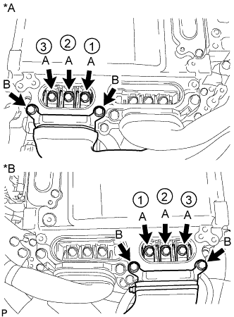
Text in Illustration *A for LHD *B for RHD Using an insulated tool, tighten the 3 bolts labeled A in the illustration.
- Torque:
- 8.0 N*m { 82 kgf*cm, 71 in.*lbf }
Note
-
The connector should be connected securely.
-
The bolts should be tightened securely.
-
Tighten the bolts in the order shown in the illustration.
-
Using an insulated tool, tighten the 2 bolts labeled B in the illustration.
- Torque:
- 8.0 N*m { 82 kgf*cm, 71 in.*lbf }
Note
-
The connector should be connected securely.
-
The bolts should be tightened securely.
-
-
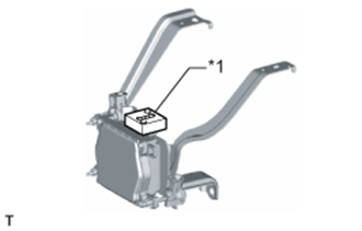
INSTALL ECM
-
Install the ECM with the 2 nuts.
- Torque:
- 12 N*m { 122 kgf*cm, 9 ft.*lbf }
Note
Any parts that have scratches, dents, etc., or that are dropped or subjected to a strong impact during servicing need to be replaced with new one.
-
Connect the 2 ECM connectors and wire clamp.
Note
-
When connecting the connectors, make sure that dirt, water or other foreign matter does not become stuck between the connectors and other parts.
-
Make sure that the 2 levers are securely locked.
-
-
for LHD:
Connect the clamp.
-
for RHD:
Connect the 2 clamps.
-
-
CONNECT SUCTION HOSE
-
Remove the attached vinyl tape from the suction hose.
-
Apply sufficient compressor oil (ND-OIL 11) to a new O-ring and the fitting surface of the compressor with motor assembly.
Compressor oil ND-OIL 11 or equivalent -
Install the O-ring on the suction hose.
-
Install the suction hose on the compressor with motor assembly with the bolt.
- Torque:
- 9.8 N*m { 100 kgf*cm, 87 in.*lbf }
-
-
CONNECT NO. 1 COOLER REFRIGERANT DISCHARGE HOSE
-
Remove the attached vinyl tape from the No. 1 cooler refrigerant discharge hose.
-
Apply sufficient compressor oil (ND-OIL 11) to a new O-ring and the fitting surface of the compressor with motor assembly.
Compressor oil ND-OIL 11 or equivalent -
Install the O-ring on the No. 1 cooler refrigerant discharge hose.
-
Install the No. 1 cooler refrigerant discharge hose on the compressor with motor assembly with the bolt.
- Torque:
- 9.8 N*m { 100 kgf*cm, 87 in.*lbf }
-
-
INSTALL NO. 1 INVERTER COOLING PIPE (for LHD)
-
Install the No. 1 inverter cooling pipe with the bolt.
- Torque:
- 13 N*m { 127 kgf*cm, 9 ft.*lbf }
-
Connect the 2 hoses.
-
Connect the 2 connectors and 2 wire harness clamps.
-
-
CONNECT NO. 7 INVERTER COOLING HOSE (for RHD)
-
Connect the No. 7 inverter cooling hose.
-
-
CONNECT NO. 5 INVERTER COOLING HOSE (for LHD)
-
Connect the No. 5 inverter cooling hose.
-
-
CONNECT NO. 2 MOTOR COOLING HOSE (for RHD)
-
Connect the No. 2 motor cooling hose.
-
-
CONNECT NO. 2 OIL COOLER OUTLET HOSE
-
Connect the No. 2 oil cooler outlet hose to the radiator assembly and slide the clip to secure it.
-
Install a new No. 1 flexible hose clamp to the radiator assembly.
-
Engage the clamp to connect the No. 2 oil cooler outlet hose to the No. 1 flexible hose clamp.
-
-
CONNECT NO. 2 OIL COOLER INLET HOSE
-
Connect the No. 2 oil cooler inlet hose to the radiator assembly and secure it with the hose clamp.
-
-
CONNECT AIR CONDITIONING HARNESS
-
Text in Illustration *1 White Tape *2 Air Conditioning Harness Connect the white tape part of the air conditioning harness to the clamp as shown in the illustration.
Note
Make sure that the air conditioning harness is securely connected.
-
Connect the 2 wire harness clamps to each bracket.
-
Connect the bracket with the bolt.
- Torque:
- 10 N*m { 102 kgf*cm, 7 ft.*lbf }
-
Text in Illustration *1 Green-colored Lock Connect the connector and lock the green-colored lock as shown in the illustration.
CAUTION:
Wear insulated gloves when performing the procedure.
-
-
CONNECT OUTLET HEATER WATER HOSE
-
Connect the outlet heater water hose.
-
Install the water hose set.
-
-
CONNECT INLET HEATER WATER HOSE
-
Connect the inlet heater water hose.
-
Install the water hose set.
-
-
CONNECT NO. 2 RADIATOR HOSE
-
Connect the No. 2 radiator hose to the water inlet with thermostat sub-assembly and secure it with the clip.
-
-
INSTALL NO. 1 RADIATOR HOSE
-
Install the No. 1 radiator hose and secure it with the 2 clamps.
-
-
CONNECT FUEL TUBE SUB-ASSEMBLY
-
Connect the fuel tube sub-assembly Click here.
-
-
CONNECT NO. 2 FUEL TUBE SUB-ASSEMBLY
-
Connect the No. 2 fuel tube sub-assembly Click here.
-
-
CONNECT NO. 3 FUEL TUBE SUB-ASSEMBLY
-
Connect the No. 3 fuel tube sub-assembly Click here.
-
-
CONNECT PURGE LINE HOSE
-
Install the clamp and connect the purge line hose.
-
-
INSTALL HEATER ACCESSORY ASSEMBLY
-
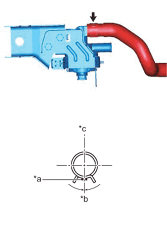
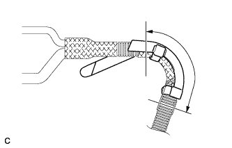
Text in Illustration *a Orange Marking *b 0 +/- 15° *c Upper Side Connect the heater water inlet hose C and attach the clip to the heater accessory assembly (heater water pump).
-
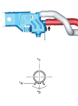
Text in Illustration *a Orange Marking *b 0 +/- 15° *c Upper Side Connect the heater water outlet hose C and attach the clip.
-
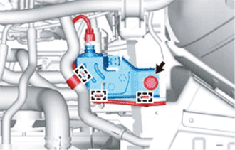
Attach the 3 clamps and install the bolt.
- Torque:
- 100 N*m { 1020 kgf*cm, 74 ft.*lbf }
-
Attach the clamp and connect the connector.
-
-
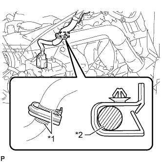
CONNECT WIRING HARNESS PROTECTOR
-
Install a new wiring harness protector to the harness.
Note
-
Securely install the 2 locks.
-
Be sure to install the wire harness protector in the location of the matchmarks placed during removal.
-
-
Using tape or equivalent, cover the area indicated in the illustration.
-
Insert the claw of a new wire harness protector into the hole in the side member and turn the claw until it touches the side member.
Note
Do not twist the electric oil pump harness more than 360° when installing it.
-
-
INSTALL OIL PUMP MOTOR CONTROLLER
-
Install the 2 oil pump motor controller brackets with the 3 bolts.
- Torque:
- 6.0 N*m { 61 kgf*cm, 53 in.*lbf }
-
Install the oil pump motor controller with bracket with the 2 bolts.
- Torque:
- 8.4 N*m { 86 kgf*cm, 74 in.*lbf }
-
-
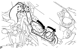
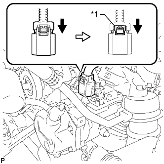
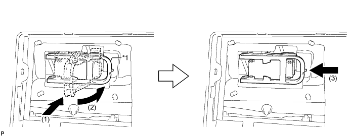
CONNECT WIRE HARNESS
-
Connect the clamp.
-
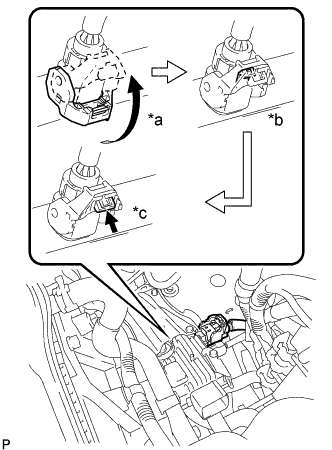
*a Raise the lever *b Lock the claw *c Push in the lock Connect the connector and securely lock the lock lever as shown in the illustration.
Note
-
Be sure to securely lock the claw of the connector.
-
Push the connector all the way in and lock the lock lever.
Tech Tips
When the connector is pushed all the way in, the lock lever will move slightly towards the lock position.
-
-
Push the lock into the lock lever to securely lock the lock lever of the connector.
-
Connect the connector to the oil pump motor controller.
-
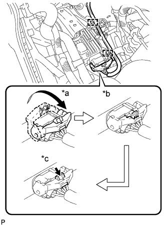
*a Raise the lever *b Lock the claw *c Push in the lock Connect the connector and securely lock the lock lever as shown in the illustration.
Note
-
Be sure to securely lock the claw of the connector.
-
Push the connector all the way in and lock the lock lever.
Tech Tips
When the connector is pushed all the way in, the lock lever will move slightly towards the lock position.
-
-
Install the clamp to the bracket.
-
Push the lock into the lock lever to securely lock the lock lever of the connector.
-
-
INSTALL AIR CLEANER CASE SUB-ASSEMBLY
-
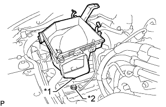
Text in Illustration *1 Pin *2 Grommet Insert the pin on the lower side of the air cleaner case into the grommet.
-
Install the air cleaner case, 2 clamps and 2 bolts.
- Torque:
- 5.0 N*m { 51 kgf*cm, 44 in.*lbf }
Note
During removal, do not lose the grommet on the underside of the air cleaner case.
-
-
INSTALL AIR CLEANER FILTER ELEMENT SUB-ASSEMBLY
-
INSTALL AIR CLEANER CAP WITH AIR CLEANER HOSE
-
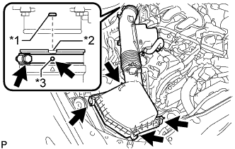
Text in Illustration *1 Bump *2 Cutout *3 Protrusion Install the air cleaner cap with air cleaner hose assembly with the 4 clamps and hose clamp.
- Torque:
- 4.0 N*m { 41 kgf*cm, 35 in.*lbf }
Note
-
Insert the protrusion on the throttle body side hose into the hole of the hose clamp.
-
Align the bump on the throttle body side with the cutout in the hose.
-
Connect the VSV hose to the air cleaner hose.
-
Connect the mass air flow meter connector and clamp to the air cleaner.
-
-
INSTALL NO. 1 AIR CLEANER INLET
-
Install the No. 1 air cleaner inlet with the bolt.
- Torque:
- 5.0 N*m { 51 kgf*cm, 44 in.*lbf }
-
-
ADD ENGINE OIL
-
Add clean engine oil.
Note
Do not allow engine oil to adhere to the moving parts of the belt tensioner, as this may cause malfunctions.
If engine oil is on the location indicated by the arrow, replace the belt tensioner.
Standard Engine Oil Oil Grade Oil Viscosity (SAE) API grade SL "energy-conserving", SM "energy-conserving", SN "resource-conserving" or ILSAC multigrade engine oil
-
0W-20
-
5W-20
-
5W-30
-
10W-30
API grade SL, SM or SN multigrade engine oil
-
15W-40
-
20W-50
Standard Capacity Item Specified Condition Drain and refill without oil filter change 5.9 liters (6.2 US. qts., 5.2 Imp. qts.) Drain and refill with oil filter change 6.3 liters (6.7 US. qts., 5.5 Imp. qts.) Dry fill 7.2 liters (7.6 US. qts., 6.3 Imp. qts.) -
-
Install the oil filler cap.
-
-
INSTALL CONNECTOR COVER ASSEMBLY
CAUTION:
Wear insulated gloves.
Note
-
Make sure that the interlock is fully engaged.
-
Do not allow any foreign objects or water to enter the inverter with converter assembly.
-
Using an insulated tool, install the connector cover assembly with the 2 bolts.
- Torque:
- 8.0 N*m { 82 kgf*cm, 71 in.*lbf }
-
-
INSTALL INVERTER TERMINAL COVER
CAUTION:
Wear insulated gloves.
-
for Type A:
-
Using an insulated tool, install the inverter terminal cover with the 2 bolts.
- Torque:
- 8.0 N*m { 82 kgf*cm, 71 in.*lbf }
Note
-
Do not touch the inverter terminal cover waterproofing rubber.
-
Visually confirm that the inverter terminal cover waterproofing rubber is securely installed before installing the inverter terminal cover.
-
Press down on the inverter terminal cover with both hands to securely connect the interlock.
-
-
for Type B:
-
Using an insulated tool, install the inverter terminal cover with the 3 bolts.
- Torque:
- 8.0 N*m { 82 kgf*cm, 71 in.*lbf }
Note
-
Do not touch the inverter terminal cover waterproofing rubber.
-
Visually confirm that the inverter terminal cover waterproofing rubber is securely installed before installing the inverter terminal cover.
-
Press down on the inverter terminal cover with both hands to securely connect the interlock.
-
-
-
INSTALL INVERTER MOTOR CABLE BRACKET ASSEMBLY
-
Install the inverter motor cable bracket assembly with the 2 bolts.
- Torque:
- 8.0 N*m { 82 kgf*cm, 71 in.*lbf }
-
Attach the 2 clamps to the inverter motor cable bracket assembly.
-
-
INSTALL INVERTER COVER
-
Attach the 2 inverter cover claws to the inverter with converter. Then attach the inverter cover with the clip.
-
-
INSTALL SERVICE PLUG GRIP
CAUTION:
Wear insulated gloves.
Note
Before connecting the service plug, check that no parts and tools remain and that the high voltage terminals and connectors are connected securely.
Text in Illustration *1 Lever - -
-
Install the service plug grip in the order shown in the illustration.
-
Insert the service plug grip and rotate the lever.
-
Slide the lever until a click sound is heard to lock the lever.
-
-
-
INSTALL LOWER HYBRID VEHICLE BATTERY COVER PANEL
CAUTION:
Perform work using insulated gloves and insulated tools.
-
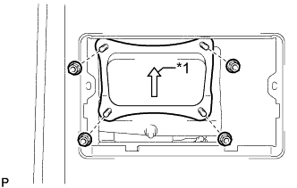
Text in Illustration *1 Arrow Install the lower hybrid vehicle battery cover panel with the 4 nuts.
Tech Tips
Be sure to install the lower hybrid vehicle battery cover panel with its arrow facing upwards.
- Torque:
- 8.0 N*m { 82 kgf*cm, 71 in.*lbf }
-
-
INSTALL NO. 1 SEAT ARMREST CAP
-
Attach the 4 guides and 4 claws to install the No. 1 seat armrest cap.
-
-
CONNECT CABLE TO AUXILIARY BATTERY NEGATIVE TERMINAL
Note
When disconnecting the cable, some systems need to be initialized after the cable is reconnected Click here.
-
INSTALL LUGGAGE COMPARTMENT TRIM COVER LH
-
Install the luggage compartment trim cover LH.
-
-
INSTALL LUGGAGE COMPARTMENT FLOOR MAT
-
Install the luggage compartment floor mat.
-
-
PERFORM INITIALIZATION
-
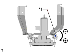
ADJUST SHIFT LEVER POSITION
-

If moving distance (A) is shorter than (B) [*1]:
Text in Illustration *a Gear Activation Point Clockwise Tech Tips
If the shift lever is moved from R to N, the moving distance of the shift lever from the original point to the gear activation point becomes longer.
-
Move the shift lever to N.
-
Loosen the 2 bolts.
-
Slightly turn the shift lever position sensor clockwise.
-
Tighten the shift lever position sensor with the 2 bolts.
- Torque:
- 5.4 N*m { 55 kgf*cm, 48 in.*lbf }
-
Recheck the shift lever position.
-
-
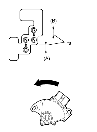
If moving distance (B) is shorter than (A) [*2]:
Text in Illustration *a Gear Activation Point Counterclockwise Tech Tips
If the shift lever is moved from D to N, the moving distance of the shift lever from the original point to the gear activation point becomes longer.
-
Move the shift lever to N.
-
Loosen the 2 bolts.
-
Slightly turn the shift lever position sensor counterclockwise.
-
Tighten the shift lever position sensor with the 2 bolts.
- Torque:
- 5.4 N*m { 55 kgf*cm, 48 in.*lbf }
-
Recheck the shift lever position.
-
-
-
INSPECT SHIFT LEVER POSITION
-
Apply the parking brake.
-
Lock the wheels with chocks to secure the vehicle.
-
Turn the power switch on (READY).
-
Move the shift lever to D and release the brake pedal.
Note
Be sure to apply the parking brake and lock the wheels with chocks to secure the vehicle.
-
Slowly move the shift lever to N and measure the moving distance (A) of the shift lever from the original point to the gear activation point.
Note
Be sure to move the shift lever slowly.
-
Move the shift lever to R and release the brake pedal.
Note
Be sure to apply the parking brake and lock the wheels with chocks to secure the vehicle.
-
Slowly move the shift lever to N and measure the moving distance (B) of the shift lever from the original point to the vehicle activation point.
Note
Be sure to move the shift lever slowly.
-
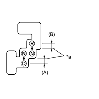
Text in Illustration *a Gear Activation Point Check that moving distances (A) and (B) shown in the illustration are almost the same.
Tech Tips
-
If moving distances (A) and (B) are almost the same, adjustment of the shift lever position is not necessary.
-
If moving distance (A) is shorter than (B), perform adjustment of the shift lever position [*1].
-
If moving distance (B) is shorter than (A), perform adjustment of the shift lever position [*2].
-
-
-
ADD ENGINE COOLANT
CAUTION:
Do not remove the radiator cap or reservoir tank cap while the engine and radiator are still hot. Pressurized hot engine coolant and steam may be released and cause serious burns.
Tech Tips
Before starting the engine to warm up the engine, turn the A/C switch off.
-
Tighten the 2 cylinder block drain cock plugs.
- Torque:
- 13 N*m { 130 kgf*cm, 9 ft.*lbf }
-
Tighten the radiator drain cock plug.
-
Remove the reservoir tank cap and radiator cap.
-
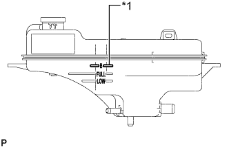
Text in Illustration *1 B Line Add coolant through the radiator reservoir tank filler opening until the coolant reaches the "B" line and install the reservoir tank cap.
Standard Capacity Radiator Core Thickness [mm] Specified Condition 16 9.4 liters (9.9 US qts, 8.3 Imp. qts) 27 9.9 liters (10.5 US qts, 8.7 Imp. qts) Note
Never use water as a substitute for engine coolant.
Tech Tips
TOYOTA vehicles are filled with TOYOTA SLLC at the factory. In order to avoid damage to the engine cooling system and other technical problems, only use TOYOTA SLLC or similar high quality ethylene glycol based non-silicate, non-amine, non-nitrite, non-borate coolant with long-life hybrid organic acid technology (coolant with long-life hybrid organic acid technology is a combination of low phosphates and organic acids).
-
Add engine coolant to the coolant filler opening and install the radiator cap.
Tech Tips
Press the No. 1 and No. 2 radiator hoses several times by hand, and then check the level of the coolant.
-
Put the engine in inspection mode Click here. [*1]
-
Warm up the engine until the thermostat opens. While the thermostat is open, circulate the coolant for several minutes. [*2]
CAUTION:
-
Wear protective gloves.
-
Be careful as the radiator hoses are hot.
-
Keep your hands away from the radiator fans.
Note
-
Immediately after starting the engine, if the radiator reservoir tank does not have any coolant, perform the following: 1) stop the engine, 2) wait until the coolant has cooled down, and 3) add coolant.
-
Do not start the engine when there is no coolant in the radiator reservoir tank.
-
Make sure that the needle does not show an abnormally high temperature.
-
If there is not enough coolant, the engine may overheat.
Tech Tips
-
Press the No. 1 and No. 2 radiator hoses several times by hand, and then check the level of the coolant.
-
The thermostat open timing can be confirmed by pressing the No. 2 radiator hose by hand, and checking when the engine coolant starts to flow inside the hose.
-
-
Stop the engine, and wait until the engine coolant cools down to ambient temperature. [*3]
-
Check the coolant level in the radiator reservoir tank. [*4]
Tech Tips
-
If the coolant level is below the "Low" line, add coolant through the radiator reservoir tank filler opening until the coolant reaches the "B" line and repeat steps [*1] through [*4].
-
If the coolant level is above the "FULL" line, drain coolant until the coolant level is between the "FULL" and "LOW" line.
-
-
-
ADD COOLANT (for Inverter)
Note
-
Do not reuse the drained coolant because it may contain foreign objects.
-
If the vehicle is driven with air in the inverter cooling system, damage may occur and the following DTCs may be set.
DTC Code Detection Item P0A04-725 Motor Electronics Coolant Temperature Sensor Circuit Intermittent P0A01-726 Motor Electronics Coolant Temperature Sensor Circuit Range / Performance P0A08-264 DC / DC Converter Status Circuit P0A78-284 Drive Motor "A" Inverter Performance P0A78-286 Drive Motor "A" Inverter Performance P0A7A-322 Generator Inverter Performance P0A7A-324 Generator Inverter Performance P0A93-346 Inverter Cooling System Performance P0A94-553 DC / DC Converter Performance P0A94-557 DC / DC Converter Performance P0AF1-276 Drive Motor Inverter Temperature Sensor "A" Circuit Intermittent / Erratic P0AEE-277 Motor Inverter Temperature Sensor "A" Circuit Range / Performance P0BD0-314 Generator Inverter Temperature Sensor Circuit Range / Erratic P0BCD-315 Generator Inverter Temperature Sensor Circuit Range / Performance P0C3C-625 DC / DC Converter Temperature Sensor "A" Intermittent / Erratic P0C39-626 DC / DC Converter Temperature Sensor "A" Range / Performance P0C41-627 DC / DC Converter Temperature Sensor "B" Intermittent / Erratic P0C3E-628 DC / DC Converter Temperature Sensor "B" Range / Performance P0C73-776 Motor Electronics Coolant Pump "A" Control Performance
-
Slowly pour coolant into the reservoir tank until it reaches the FULL line.
Standard Capacity Item Specified Condition for LHD 3.1 liters (3.3 US qts, 2.7 Imp. qts.) for RHD 2.9 liters (3.0 US qts, 2.6 Imp. qts.) Note
To prevent foreign matter such as dust or dirt from entering the cooling system, make sure to confirm that the container used to add coolant is clean and free of foreign matter such as dust or dirt.
-
When using the GTS:
-
Connect the GTS to the DLC3.
-
Turn the power switch on (IG).
-
Enter the following menus: Powertrain / Hybrid Control / Active Test / Activate the Water Pump.
-
Keep the coolant at the FULL line in the reservoir tank to compensate for the drop in coolant level when the air bleeds.
Standard Air bleeding from the inverter cooling system is completed when the noise made by the inverter water pump assembly becomes smaller and the circulation of coolant in the reservoir tank improves. Tech Tips
-
If free spinning of the inverter water pump is detected for approximately 5 seconds, failsafe control will be activated to suspend the operation of the pump for approximately 15 seconds and resume operation for approximately 4 seconds repeatedly. Operation of the inverter water pump will return to normal if coolant is added.
-
Loud noise made by the inverter water pump and poor circulation of coolant in the reservoir tank indicates that there is air in the cooling system.
-
-
-
When not using the GTS:
-
Turn the power switch on (READY).[*1]
-
Turn the power switch off and add coolant to the FULL line because the coolant level drops as the air bleeds.[*2]
Note
-
Be sure to turn the power switch off before adding SLLC.
-
Do not work on the components in the engine compartment while the vehicle is in the READY-on state because the engine is in intermittent operation.
-
-
Repeat steps [*1] and [*2] until air bleeding from the cooling system is completed.
Standard Air bleeding from the inverter cooling system is completed when the noise made by the inverter water pump assembly becomes smaller and the circulation of coolant in the reservoir tank improves. Tech Tips
Loud noise made by the inverter water pump and poor circulation of coolant in the reservoir tank indicates that there is air in the cooling system.
-
-
After the air is completely bled from the cooling system, tighten the reservoir tank cap.
-
Add coolant to the FULL line of the reservoir tank.
-
-
CHARGE AIR CONDITIONING SYSTEM WITH REFRIGERANT (for HFC-134a(R134a))
-
Perform vacuum purging using a vacuum pump or appropriate equipment.
-
Charge the air conditioning system with refrigerant.
Refrigerant type HFC-134a (R134a) 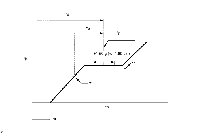
Text in Illustration *a Sub-cool System *b High Pressure *c Refrigerant Amount *d Standard charge amount *e Charge additional 100 g (3.5 oz.) *f Point where bubbles disappear *g Mean value in proper range *h Overcharged Standard charge amount for 2GR-FXE 450 to 550 g (15.9 to 19.4 oz.) for 2AR-FSE 520 to 620 g (18.3 to 21.8 oz.) - SST
- 09985-20010 ( 09985-02010, 09985-02050, 09985-02060, 09985-02070, 09985-02080, 09985-02090, 09985-02110, 09985-02130, 09985-02140, 09985-02150 )
Note
-
Do not turn the A/C switch on before charging the air conditioning system with refrigerant. Doing so may cause the compressor to work without refrigerant, resulting in overheating of the compressor.
-
The refrigerant amount should be checked by quantity (weight).
Tech Tips
Make sure that sufficient refrigerant is available to recharge the system when using a refrigerant recovery unit. Refrigerant recovery units are not always able to recover 100% of the refrigerant from an air conditioning system.
-
-
INSPECT FOR COOLANT LEAK
CAUTION:
Do not remove the radiator cap or reservoir tank cap while the engine and radiator are still hot. Pressurized hot engine coolant and steam may be released and cause serious burns.
Note
Before performing each inspection, turn the A/C switch off.
-
Remove the reservoir tank cap.
-
Fill the radiator with coolant and attach a radiator cap tester.
-
Put the engine in inspection mode Click here.
-
Warm up the engine.
-
Using a radiator cap tester, increase the pressure inside the radiator to 137 kPa (1.4 kgf/cm2, 20 psi), and check that the pressure does not drop.
If the pressure drops, check the hoses, radiator and engine water pump for leaks. If no external leaks are found, check the heater core, cylinder block and cylinder head.
-
-
INSPECT COOLANT LEAK (for Inverter)
-
Remove the reservoir tank cap (for inverter).
CAUTION:
To avoid the danger of being burned, do not remove the reservoir tank cap while the coolant for the inverter is still hot.
-
Install the radiator cap tester.
-
Pump the radiator cap tester to 137 kPa (1.4 kgf/ cm2, 20 psi), and then check that the pressure does not drop.
Tech Tips
If the pressure drops, check the hoses, radiator, water pump, inverter with converter, and hybrid vehicle transaxle assembly for leaks.
-
Reinstall the reservoir tank cap (for inverter).
-
-
INSPECT FOR OIL LEAK
-
Put the engine in inspection mode Click here.
-
Start the engine. Make sure that no oil leaks from the connection point of the oil filter cap.
-
-
INSPECT FOR FUEL LEAK
-
Connect the GTS to the DLC3.
-
Turn the power switch on (IG).
Note
Do not start the engine.
-
Turn the GTS on.
-
Enter the following menus: Powertrain / Engine and ECT / Active Test / Control the Fuel Pump / Speed.
-
-
Check the fuel pump operation.
-
Check for pressure in the fuel inlet tube from the fuel line. Check that the sound of fuel flowing in the fuel tank can be heard.
If no sound can be heard, check the integration relay, fuel pump, ECM and wiring connector.
-
-
Inspect for fuel leaks.
-
Check that there are no fuel leaks anywhere in the system after performing maintenance.
If there is a fuel leak, repair or replace parts as necessary.
-
-
-
INSPECT FOR EXHAUST GAS LEAK
Tech Tips
If an exhaust gas leak has been repaired, perform an inspection following the repair Click here.
If gas is leaking, tighten the areas necessary to stop the leak. Replace damaged parts as necessary.
-
CHECK FOR REFRIGERANT GAS LEAK (for HFC-134a(R134a))
-
After recharging the air conditioning system with refrigerant, check for refrigerant leaks using a halogen leak detector.
-
Carry out the test under the following conditions:
-
Power switch off.
-
Secure good ventilation (the halogen leak detector may react to volatile gases which are not refrigerant, such as gasoline vapor and exhaust gas).
-
Repeat the inspection 2 or 3 times.
-
Measure the pressure to make sure that there is some refrigerant remaining in the air conditioning system (pressure when the compressor is off: approx. 392 to 588 kPa (3.9 to 5.9 kgf/cm2, 57 to 85 psi)).
-
-
Text in Illustration *1 Halogen Leak Detector *a Check for Leak Using a halogen leak detector, check for refrigerant leaks from the air conditioning system.
-
If a refrigerant leak is not detected from the drain hose, remove the blower motor control from the cooling unit. Insert the halogen leak detector sensor into the unit and check for a leak.
-
Disconnect the pressure sensor connector and leave it for approximately 20 minutes. Bring the halogen leak detector close to the pressure sensor and check for a leak.
Tech Tips
When checking for leaks, the presence of oily dirt at a joint can indicate a leak.
-
-
INSTALL FRONT WHEEL
- Torque:
- 103 N*m { 1050 kgf*cm, 76 ft.*lbf }
-
PLACE FRONT WHEELS FACING STRAIGHT AHEAD
-
CHECK AND ADJUST FRONT WHEEL ALIGNMENT
-
VARIABLE GEAR RATIO STEERING SYSTEM CALIBRATION (w/ VGRS)
-
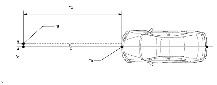
ADJUST MILLIMETER WAVE RADAR SENSOR ASSEMBLY (w/ Dynamic Radar Cruise Control System)
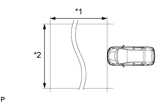
Text in Illustration *1 Approx. 10 m (32.8 ft.) *2 Approx. 14 m (45.9 ft.) Note
-
Perform measurements on a level surface.
-
Make sure that no large pieces of metal are within a 10 m (32.8 ft.) x 14 m (45.9 ft.) area in front of the vehicle. If possible, the surrounding area should also be free of large metal objects.
-
Before adjusting the radar beam axis, prepare the vehicle as follows.
-
Remove all excess weight from the vehicle (luggage, heavy objects, etc.).
-
Check the tire pressure and adjust it if necessary Click here.
-
-
Text in Illustration *1 Level Check and adjust the vertical direction of the radar sensor.
-
Remove dust, oil and foreign matter from the radar sensor's level rack.
-
Set a level on the radar sensor's level rack.
-
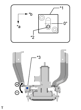
Text in Illustration *1 Level *2 Air Bubble *3 Bolt A *a FR *b LH Check that the level's air bubble is within the red frame.
OK Level's air bubble is within the red frame. If the bubble is not within the red frame, use a screwdriver to adjust bolt A until the air bubble is within the red frame.
Tech Tips
-
The adjustable range within the level's red frame is +/- 0.2°.
-
The target angle is +0.2° (upward angle of 0.2°).
Adjustment Adjustment Direction Adjustment Procedure Adjustment Angle Vertical adjustment Upward direction: Turn bolt A to negative (-) side For 1 complete turn of screwdriver, sensor moves about 0.12° Downward direction: Turn bolt A to positive (+) side
-
-
-
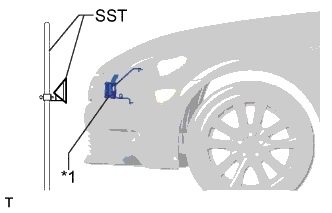
Text in Illustration *1 Millimeter Wave Radar Sensor Adjust the reflector height.
-
Adjust the reflector so that the center of SST reflector is the same height as the millimeter wave radar sensor.
- SST
- 09870-60000 ( 09870-60010 )
- 09870-60040
Tech Tips
Prepare a 10 m (32.8 ft.) string, a string with a sharp-pointed weight (plumb bob), and a 5 m (16.4 ft.) tape measure.
-
-
Place the reflector.
-
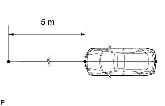
Hang the string (with weight) from the center of the vehicle's rear emblem. Mark the vehicle's rear center point on the ground. Repeat for the front of the vehicle.
-
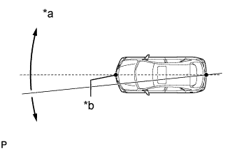
Text in Illustration *a Adjust Center By Moving String To Right And Left *b Extend String Through Front Center Mark Set one end of the 10 m (32.8 ft.) string on the vehicle's rear center point. Run the string over the vehicle's front center point to a position 5 m (16.4 ft.) beyond the vehicle's front center point as shown in the illustration. Mark the 5 m (16.4 ft.) position.
-
Place the reflector (SST) at the marked position.
Note
Perform the operation as precisely as possible.
Text in Illustration *a Reflector (SST) Placement Point *b Millimeter Wave Radar Sensor Position *c 5 m (16.4 ft.) *d 13.1 mm (0.516 in.)
-
-
Check the radar beam axis.
-
When using the GTS:
-
Connect the GTS to the DLC3.
-
Turn the power switch on (IG).
-
Turn the GTS on, and turn the cruise control main switch on.
-
Select "Connect to Vehicle".
-
Select each item on the display screen and proceed to the next screen.
-
Under "System Selection Menu", select "Radar Cruise".
-
Select "Utility".
-
Select "Beam Axis Adjustment" and proceed to the next screen.
Tech Tips
A buzzer will sound for 1 second.
-
Follow the GTS display, and continue with the adjustment.
Note
-
Turn the cruise control main switch on before pressing "Next".
-
Make sure there is at least 20 cm (7.87 in.) between the radar sensor and any nearby individuals.
-
-
-
Check the following items on the radar cruise divergence data screen.
Note
While using the GTS beam axis adjustment mode, the actual direction and angle of the radar sensor may be different from the GTS data. In such a case, the deviation is displayed on the multi-information display in the combination meter.
-
Confirm that the distance value is approximately 5 m (16.4 ft.).
Tech Tips
-
A value between 0.0 m (0.0 ft.) and 6.3 m (20.7 ft.) should be indicated.
-
If the distance is 0.0 m (0.0 ft.), the sensor cannot detect the target. Reconfirm that there is no metal in the specified area in front of the vehicle (refer to the Notice at the beginning of this adjustment procedure).
-
-
Confirm that the left/right side value is between 0.0 m (0.0 ft.) and 6.3 m (20.7 ft.).
Tech Tips
If the distance is 0.0 m (0.0 ft.), the sensor cannot detect the target. Reconfirm that there is no metal in the specified area in front of the vehicle (refer to the Notice at the beginning of this adjustment procedure).
-
-
-
Check and adjust the horizontal direction of the radar sensor.
-
Check that the divergence of the radar beam axis is 0°.
Standard 0° (Both right and left) If the axis is not as specified, use a screwdriver to adjust bolt B until the divergence of the radar beam axis is 0°.
-
Text in Illustration *1 Bolt B Based on the measured divergence of the beam axis, turn and adjust bolt B for horizontal adjustment of the millimeter wave radar sensor using a screwdriver.
Adjustment Adjustment Direction Adjustment Procedure Adjustment Angle Horizontal adjustment Right direction: Turn bolt B to positive (+) side. For 1 complete turn of screwdriver, sensor moves about 0.07° Left direction: Turn bolt B to negative (-) side. Tech Tips
If the value does not change to 0°, it is possible that the sensor is aiming at something different. Reconfirm that there are no reflective materials in the surrounding area.
-
Finish the beam axis adjustment.
-
Disconnect the GTS from the DLC3.
-
-
Recheck and readjust the vertical direction of the radar sensor.
-
Text in Illustration *1 Level Set a level on the radar sensor's level rack.
-
Text in Illustration *1 Level *2 Air Bubble *3 Bolt A *a FR *b LH Check that the level's air bubble is within the red frame.
OK Level's air bubble is within the red frame. If the bubble is not within the red frame, use a screwdriver to adjust bolt A until the level's air bubble is within the red frame.
Tech Tips
-
The adjustable range within the red frame is +/- 0.2°.
-
The target angle is + 0.2° (upward angle of 0.2°).
Adjustment Adjustment Direction Adjustment Procedure Adjustment Angle Vertical adjustment Upward direction: Turn bolt A to negative (-) side For 1 complete turn of screwdriver, sensor moves about 0.12° Downward direction: Turn bolt A to positive (+) side
-
-
-
-
ADJUST NIGHT VIEW CAMERA ASSEMBLY
-
When the night view camera assembly is replaced, perform adjust night view camera assembly Click here.
-
-
INSPECT THROTTLE WITH MOTOR BODY ASSEMBLY
Note
Be sure to perform this procedure after reassembling the throttle body assembly, removing and reinstalling any throttle body component or replacing the ECM.
-
Disconnect the cable from the negative (-) auxiliary battery terminal. Wait at least 60 seconds and reconnect the cable.
-
Connect the GTS to the DLC3 and clear the DTCs Click here.
-
Put the engine in inspection mode (maintenance mode) Click here.
-
Start the engine and check that the MIL is not illuminated. After the engine is warmed up, check that the idle speed is within the specified range when the A/C is switched off.
Standard Condition Engine Idle Speed A/C switched off 950 to 1050 rpm Note
-
If the accelerator pedal is operated, perform the above steps again.
-
Be sure to perform this step with all accessories off.
-
Make sure that park (P) is selected.
-
-
Perform a road test and confirm that there are no abnormalities.
-
-
INSPECT IGNITION TIMING
-
Put the engine in inspection mode Click here.
-
Warm up the engine and stop the engine.
Note
A warmed up engine should have an engine coolant temperature of over 80°C (176°F), and an engine oil temperature of 60°C (140°F), and the engine speed should be stabilized.
-
When using the GTS:
-
Connect the GTS to the DLC3.
-
Start the engine and idle it.
-
Turn the GTS on.
-
Enter the following menus: Powertrain / Engine and ECT / Data List / IGN Advance.
Standard ignition timing 8 to 18° BTDC at idle Note
When checking the ignition timing, the transmission should be in park.
Tech Tips
Refer to the GTS operator's manual for further details.
-
Check that the ignition timing advances immediately when the engine speed is increased.
-
Enter the following menus: Powertrain / Engine and ECT / Active Test / Connect the TC and TE1.
-
Monitor IGN Advance.
-
Perform the Active Test.
Standard ignition timing 8 to 12° BTDC at idle Note
When checking the ignition timing, the transmission should be in park.
Tech Tips
Refer to the GTS operator's manual for further details.
-
-
When not using the GTS:
-
Remove the V-bank cover sub-assembly.
-
Connect the tester probe of a timing light to the wire of the ignition connector for the No. 1 cylinder.
Note
Use a timing light which can detect the primary signal.
-
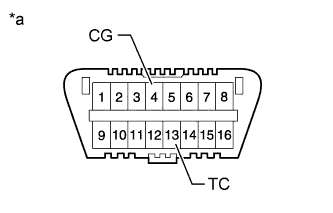
Text in Illustration *a Front view of DLC3 Using SST, connect terminals 13 (TC) and 4 (CG) of the DLC3.
- SST
- 09843-18040
Note
-
Confirm the terminal numbers before connecting them. Connecting the wrong terminals can damage the engine.
-
When checking the ignition timing, the transmission should be in park.
-
Using a timing light, check the ignition timing.
Standard ignition timing 8 to 12° BTDC at idle -
Remove SST from the DLC3.
-
Check the ignition timing.
Standard ignition timing 8 to 18° BTDC at idle -
Check that the ignition timing advances immediately when the engine speed is increased.
-
Disconnect the timing light from the engine.
-
Install the V-bank cover sub-assembly.
-
-
-
INSPECT ENGINE IDLE SPEED
-
Put the engine in inspection mode Click here.
-
Warm up and stop the engine.
Note
A warmed up engine should have an engine coolant temperature of over 80°C (176°F) and an engine oil temperature of 60°C (140°F), and the engine speed should be stabilized.
-
When using the GTS:
-
Connect the GTS to the DLC3.
Note
Switch off all accessories and A/C before connecting the GTS.
-
Race the engine at 2500 rpm for approx. 90 seconds.
-
Turn the GTS on.
-
Enter the following menus: Powertrain / Engine and ECT / Data List / Engine Speed.
Standard idle speed 950 to 1050 rpm Note
When checking the idle speed, the transmission should be in park.
Tech Tips
Refer to the GTS operator's manual for further details.
If the idle speed is not as specified, check the air intake system.
-
Disconnect the GTS from the DLC3.
-
-
When not using the GTS:
-
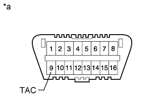
Text in Illustration *a Front view of DLC3 Using SST, connect the tachometer probe to terminal 9 (TAC) of the DLC3.
- SST
- 09843-18030
Note
Confirm the terminal numbers before connecting them. Connecting the wrong terminals can damage the engine.
-
Race the engine at 2500 rpm for approx. 90 seconds.
-
Check the idle speed.
Standard idle speed 950 to 1050 rpm Note
When checking the idle speed, the transmission should be in park.
If the speed is not as specified, check the air intake system.
-
Disconnect the tachometer from the DLC3.
-
-
-
INSPECT CO/HC
Tech Tips
This is a check for determining whether or not the idle CO/HC complies with regulations.
-
Put the engine in inspection mode Click here.
-
Start the engine.
-
Keep the engine speed at 2500 rpm for approx. 180 seconds.
-
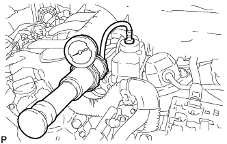
Insert the CO/HC meter testing probe at least 40 cm (1.31 ft.) into the tailpipe during idling.
-
Immediately check CO/HC concentration at idle and/or 2500 rpm.
Tech Tips
-
When performing the 2 mode (2500 rpm and idle) test, follow the measurement order prescribed by the applicable local regulations.
-
If the CO/HC concentration does not comply with regulations, troubleshoot in the order given below.
-
Check the DTCs Click here.
-
See the table below for possible causes, and then inspect and correct the applicable causes if necessary.
CO HC Symptom Causes Normal High Rough idle
-
1. Faulty ignitions
-
Incorrect timing
-
Fouled, shorted or improperly gapped plugs
-
2. Leaky intake and exhaust valves
-
3. Leaky cylinder
Low High Rough idle
(Fluctuating HC reading)
-
1. Vacuum leaks
-
PCV hose
-
Intake manifold
-
Throttle body
-
2. Lean mixture causing misfire
High High Rough idle
(Black smoke from exhaust)
-
1. Restricted air filter
-
2. Faulty fuel SFI system
-
Faulty pressure
-
Defective engine coolant temperature sensor
-
Faulty ECM
-
Faulty injector
-
Faulty throttle position sensor
-
Faulty mass air flow meter
-
-
-
-
INSPECT ENGINE COOLANT LEVEL
-
Check that the engine coolant level is between the "LOW" and "FULL" lines when the engine is cold.
If the engine coolant level is low, check for leaks and add TOYOTA Super Long Life Coolant (SLLC) or similar high quality ethylene glycol based non-silicate, non-amine, non-nitrite and non-borate coolant with long-life hybrid organic acid technology to the "FULL" line.
Note
Do not substitute plain water for engine coolant.
-
-
INSPECT COOLANT LEVEL IN RESERVOIR TANK (for Inverter)
-
The coolant should be between the LOW and FULL lines when the coolant for the inverter is cold.
Tech Tips
If the coolant level is low, check for leaks and add TOYOTA Super Long Life Coolant (SLLC) or similar high quality ethylene glycol based non-silicate, non-amine, non-nitrite, and non-borate coolant with long-life hybrid organic acid technology up to the FULL line.
-
-
INSPECT ENGINE OIL LEVEL
-
Put the engine in inspection mode Click here.
-
Warm up and stop the engine, and then wait for 5 minutes. The oil level should be between the dipstick's low level mark and full level mark.
If low, check for leakage and add oil up to the full level mark.
Note
Do not add engine oil to above the full level mark.
-
-
INSTALL NO. 2 ENGINE UNDER COVER
-
Install the No. 2 engine under cover with the 4 screws and 2 grommets.
-
-
INSTALL FRONT SUSPENSION MEMBER BRACE
-
Install the front suspension member brace with the clip and 4 bolts.
- Torque:
- 52 N*m { 530 kgf*cm, 38 ft.*lbf }
-
-
INSTALL REAR ENGINE UNDER COVER LH
-
Install the rear engine under cover LH with the screw.
-
-
INSTALL REAR ENGINE UNDER COVER RH
Tech Tips
Install the RH side following the same procedure as for the LH side.
-
INSTALL ENGINE UNDER COVER
-
Install the engine under cover with the 13 screws and 3 clips.
-
-
INSTALL V-BANK COVER SUB-ASSEMBLY
-
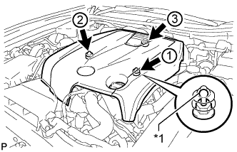
Text in Illustration *1 Tip (Round Portion) Attach the 3 clips in the order shown in the illustration to install the V-bank cover.
Note
-
Securely attach the clips.
-
If the clips are forcibly attached or struck with an object, they may be damaged.
-
Do not apply any oil to the tips (round portions).
-
-
-
INSTALL COOL AIR INTAKE DUCT SEAL
-
Install the cool air intake duct seal with the 7 clips.
-
-
INSTALL ENGINE ROOM SIDE COVER
-
Install the engine room side cover with the 4 clips.
-