FRAME WIRE INSTALLATION

-
INSTALL WIRE HARNESS CLAMP BRACKET B (for LHD)
-
Install the wire harness clamp bracket B with the 2 bolts.
- Torque:
- 13 N*m { 133 kgf*cm, 10 ft.*lbf }
-
-
INSTALL NO. 4 FLOOR WIRE
CAUTION:
Wear insulated gloves.
-
for LHD:
Install the No. 4 floor wire with 5 new stud clamps.
-
for RHD:
Install the No. 4 floor wire with 4 new stud clamps.
-
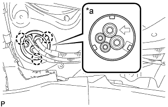
Text in Illustration *a Vehicle Under Side 
Front Attach the 3 claws and insert the frame wire into the floor panel hole.
Tech Tips
The arrow should point toward the front of the vehicle.
-
Connect the 2 wire harness clamps to the floor panel.
-
Install the bolt.
- Torque:
- 13 N*m { 133 kgf*cm, 10 ft.*lbf }
-
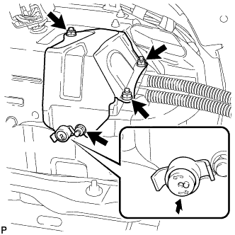
Install the 2 bolts and attach the clamp.
- Torque:
- 13 N*m { 133 kgf*cm, 10 ft.*lbf }
-
for LHD:
-
Install the nut, and attach the 2 claws to the relay block.
- Torque:
- 11 N*m { 107 kgf*cm, 8 ft.*lbf }
-
Connect the connector and attach the 4 wire harness clamps.
-
Install the 2 bolts, 2 nut and attach the wire harness clamp.
- Torque:
- for bolts
- 13 N*m { 133 kgf*cm, 10 ft.*lbf }
- for nuts
- 8.0 N*m { 82 kgf*cm, 71 in.*lbf }
-
Install the 4 nuts and attach the 2 wire harness clamps.
- Torque:
- 8.0 N*m { 82 kgf*cm, 71 in.*lbf }
-
-
for RHD:
-
Install the nut, and attach the 2 claws.
- Torque:
- 11 N*m { 107 kgf*cm, 8 ft.*lbf }
-
Install the bolt and attach the 2 wire harness clamps.
-
-
Remove the bolt and connector cover.
Note
-
Make sure to pull the connector cover assembly straight up, as a connector is connected to the bottom of the cover.
-
Do not allow any foreign objects or water to enter the inverter with converter.
-
-
Using an insulated tool, connect the No. 4 floor wire with the bolt.
- Torque:
- 8.0 N*m { 82 kgf*cm, 71 in.*lbf }
Note
-
Do not damage the terminals, connector housings or inverter with converter when connecting them.
-
Do not touch the connector waterproofing rubber or terminals.
-
Do not allow any foreign objects or water to enter the inverter with converter.
-
Make sure that the connectors are fully engaged.
-
Make sure that the connector does not come out when its body is pulled.
-
Connect the air conditioner harness to the inverter with converter.
Note
-
Do not damage the terminals, connector housings or inverter with converter when connecting them.
-
Do not touch the connector waterproofing rubber or terminals.
-
Do not allow any foreign objects or water to enter the inverter with converter.
-
Make sure that the connectors are fully engaged.
-
Make sure that the connector does not come out when its body is pulled.
-
-
Temporarily install the bolt with connector cover.
CAUTION:
Wear insulated gloves.
-
Connect the connector and wire harness clamp.
-
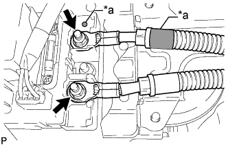
Text in Illustration *a Red Mark Using an insulated tool, connect the 2 frame wires with the 2 nuts.
- Torque:
- 9.0 N*m { 92 kgf*cm, 80 in.*lbf }
Note
Be sure to match the red marks on the frame wires to the red marks on the HV relay and install the frame wires.
-
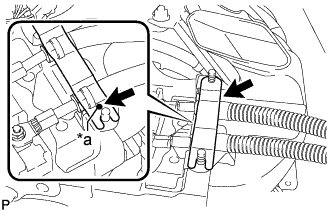
Text in Illustration *a Matchmark Install the battery shield contact.
Note
Correctly align the matchmark when installing the battery shield contact.
-
-
CHECK HIGH VOLTAGE CABLE CONNECTION CONDITION
CAUTION:
Wear insulated gloves and protective goggles.
-
Check that each wire harness is being installed securely.
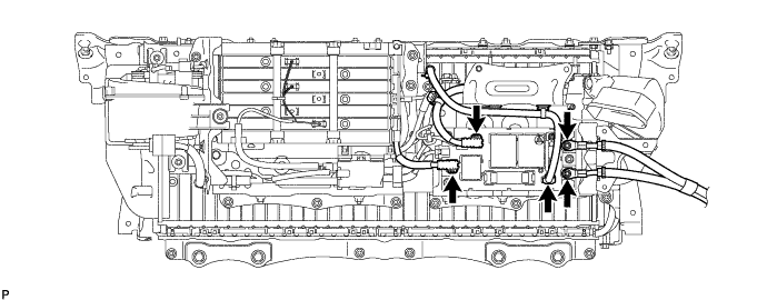
Text in Illustration *1 No. 4 Floor Wire - - Note
-
Make sure that the ends of the frame wire are not crossed over each other.
-
Be sure to connect the frame wire to the correct terminals as shown in the illustration.
-
The connectors should be connected securely.
-
The nuts should be fastened securely.
-
Make sure that the 2 plastic covers are engaged securely.
-
-
-
INSTALL NO. 4 HYBRID VEHICLE BATTERY SHIELD SUB-ASSEMBLY
-
Using an insulated tool, install the No. 4 hybrid vehicle battery shield with the 4 nuts.
- Torque:
- 8.0 N*m { 82 kgf*cm, 71 in.*lbf }
-
Install the battery cover lock striker, then push the button to lock it.
-
Install the No. 1 hybrid battery intake duct LH with the 2 clips.
-
-
INSTALL AUXILIARY BATTERY TERMINAL
-
Insert the No. 4 floor wire into the floor panel hole and install the grommet.
-

Text in Illustration *1 Battery Terminal *2 Arrow *a Vehicle Under Side Install the auxiliary battery terminal with nut.
- Torque:
- 6.8 N*m { 69 kgf*cm, 60 in.*lbf }
Tech Tips
The arrow should point toward the battery terminal.
-
Install the connector cover.
-
-
INSTALL NO. 14 WIRE HARNESS PROTECTOR
-
Install the No. 14 wire harness protector with the nut and clamp.
- Torque:
- 5.5 N*m { 56 kgf*cm, 49 in.*lbf }
-
-
INSTALL NO. 13 WIRE HARNESS PROTECTOR
-
Attach the 2 clamps with a new No. 13 wire harness protector.
-
-
INSTALL NO. 4 FRONT FLOOR HEAT INSULATOR
-
Install the No. 4 floor heat insulator with the 2 bolts.
- Torque:
- 4.9 N*m { 50 kgf*cm, 43 in.*lbf }
-
-
INSTALL WIRE HARNESS CLAMP BRACKET A
-
Install the wire harness clamp bracket A with the 2 nuts.
- Torque:
- 8.0 N*m { 82 kgf*cm, 71 in.*lbf }
-
-
INSTALL REAR SEAT ASSEMBLY
-
INSTALL FUEL TANK ASSEMBLY
-
w/o Canister Pump Module:
-
w/ Canister Pump Module:
-
-
INSTALL ENGINE ASSEMBLY WITH TRANSAXLE
-
INSTALL SERVICE PLUG GRIP
-
CONNECT CABLE TO AUXILIARY BATTERY NEGATIVE TERMINAL
Note
When disconnecting the cable, some systems need to be initialized after the cable is reconnected Click here.
-
INSTALL LUGGAGE COMPARTMENT TRIM COVER LH
-
Install the luggage compartment trim cover.
-
-
INSTALL LUGGAGE COMPARTMENT FLOOR MAT
-
Install the luggage compartment floor mat.
-