HV BATTERY REMOVAL

-
PRECAUTION
CAUTION:
Be sure to read Precaution thoroughly before servicing Click here.
Note
After turning the power switch off, waiting time may be required before disconnecting the cable from the auxiliary battery negative (-) terminal. Therefore, make sure to read the disconnecting the cable from the auxiliary battery negative (-) terminal notices before proceeding with work Click here.
-
When disposing of an HV battery, make sure to return it through an authorized collection agent who is capable of handling it safely. If the HV battery is returned via the manufacturer specified route, it will be returned properly and in a safe manner by an authorized collection agent.
CAUTION:
-
Accidents such as electric shock may result if the HV battery is disposed of improperly or abandoned. Therefore, make sure to return all HV batteries through an authorized collection agent.
-
After removing the HV battery, keep it away from water. Exposure to water may cause the HV battery to produce heat, resulting in a fire.
-
-
-
READ OUTPUT DTC
-
Check for DTCs Click here.
Note
Confirm that P0AA6 (Hybrid Battery Voltage System Isolation Fault) is not output before performing removal or installation work on the internal parts of the battery. If the DTC is output, perform troubleshooting procedures first.
-
-
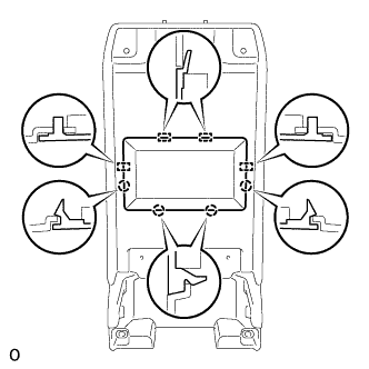
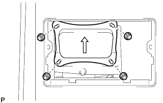
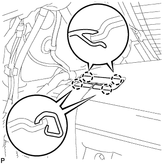
REMOVE LUGGAGE COMPARTMENT FLOOR MAT
-
Remove the luggage compartment floor mat.
-
-
REMOVE LUGGAGE COMPARTMENT TRIM COVER LH
-
Remove the luggage compartment trim cover LH.
-
-
DISCONNECT CABLE FROM AUXILIARY BATTERY TERMINAL
Note
When disconnecting the cable, some systems need to be initialized after the cable is reconnected Click here.
-
Disconnect the cable from the auxiliary battery negative (-) terminal.
Tech Tips
Both cables should be disconnected to prevent the AMD terminal from shorting to ground.
-
Remove the terminal cover.
-
Remove the nut and disconnect the cable from the auxiliary battery positive (+) terminal.
Tech Tips
Both cables should be disconnected to prevent the AMD terminal from shorting to ground.
-
-
REMOVE NO. 1 SEAT ARMREST CAP
-
Detach the 4 claws and 4 guides, and remove the No. 1 seat armrest cap.
-
-
REMOVE LOWER HYBRID VEHICLE BATTERY COVER PANEL
CAUTION:
Perform work using insulated gloves and insulated tools.
-
Remove the 4 nuts and lower hybrid vehicle battery cover panel.
-
-
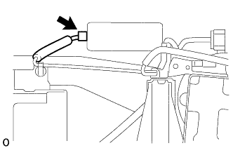
REMOVE SERVICE PLUG GRIP
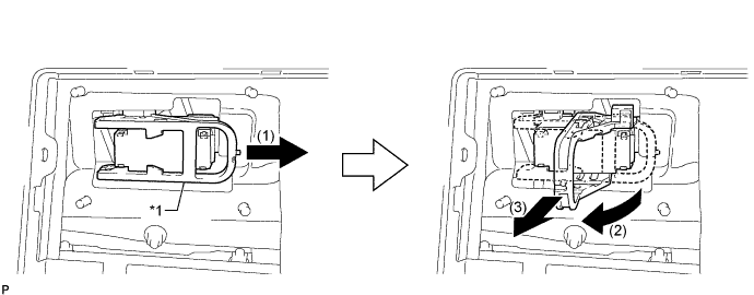
Text in Illustration *1 Lever - -
-
Remove the service plug grip in the order shown in the illustration.
CAUTION:
-
Wear insulated gloves.
-
Remove the service plug grip to interrupt a high voltage circuit at the time of the check.
-
Keep the removed service plug grip in your pocket to prevent other technicians from accidentally reconnecting it while you are servicing the vehicle.
-
After disconnecting the service plug grip, wait at least 10 minutes before touching any of the high-voltage connectors or terminals.
-
Never turn the power switch on (READY) with the service plug grip removed as malfunctions may occur.
Tech Tips
-
Waiting for at least 10 minutes is required to discharge the high-voltage capacitor inside the inverter with converter assembly.
-
High voltage wiring connectors are orange.
-
Slide the lever and release the lock.
-
Raise the lever and pull the service plug grip to remove it.
-
-
-
REMOVE INVERTER COVER
-
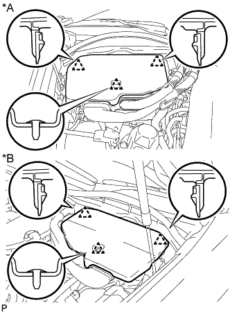
Text in Illustration *A for LHD *B for RHD Raise the front of the inverter cover to detach the clip. Then remove the 2 inverter cover clips from the bracket, and remove the inverter cover.
-
-
REMOVE CONNECTOR COVER ASSEMBLY
CAUTION:
-
Do not touch the high voltage connectors and terminals for 10 minutes after the service plug grip is removed.
-
Wear insulated gloves.
Note
Do not start the hybrid system with the service plug grip removed because it may cause a malfunction.
-
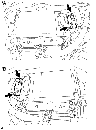
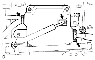
Text in Illustration *A for LHD *B for RHD Using an insulated tool, remove the 2 bolts and connector cover assembly.
Note
-
Make sure to pull the connector cover assembly straight up, as a connector is connected to the bottom of the connector cover assembly.
-
Do not allow any foreign objects or water to enter the inverter with converter assembly.
-
-
-
CHECK TERMINAL VOLTAGE
CAUTION:
Wear insulated gloves.
Note
Do not allow any foreign objects or water to enter the inverter with converter assembly.
-
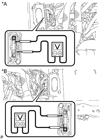
Text in Illustration *A for LHD *B for RHD Using a voltmeter, measure the voltage between the terminals of the 2 phase connectors.
Standard voltage 0 V Tech Tips
Use a measuring range of DC 750 V or more on the voltmeter.
-
-
INSTALL CONNECTOR COVER ASSEMBLY
CAUTION:
Wear insulated gloves.
Note
-
Make sure that the interlock is fully engaged.
-
Do not allow any foreign objects or water to enter the inverter with converter assembly.
-
Using an insulated tool, install the connector cover assembly with the 2 bolts.
- Torque:
- 8.0 N*m { 82 kgf*cm, 71 in.*lbf }
-
-
INSTALL INVERTER COVER
-
Attach the 2 inverter cover claws to the inverter with converter. Then attach the inverter cover with the clip.
-
-
REMOVE REAR SEAT ASSEMBLY
-
REMOVE REAR DOOR SCUFF PLATE LH
-
Place your hands on the inner portion of the rear door scuff plate LH and detach the 2 claws labeled A, 6 claws labeled B and 2 claws labeled C in the order shown in the illustration.
-
Raise the rear door scuff plate LH to detach the 4 clips on the outer side and remove it.
Text in Illustration *1 Claw A *2 Claw B *3 Claw C - -
-
-
REMOVE REAR SEAT SIDE GARNISH LH
-
Detach the 4 claws and guide and remove the rear seat side garnish LH.
-
-
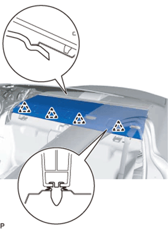
REMOVE INNER ROOF SIDE GARNISH LH
-
w/ Rear Sunshade:
-
Detach the 4 clips.
-
Detach the 3 guides and the end of the rear window shade assembly, and then remove the inner roof side garnish LH.
Text in Illustration *1 End Of The Rear Window Shade Assembly *2 Guide
-
-
w/o Rear Sunshade:
-
Detach the 4 clips and 3 guides and remove the inner roof side garnish LH.
-
-
-
REMOVE REAR DOOR SCUFF PLATE RH
Tech Tips
Use the same procedure described for the LH side.
-
REMOVE REAR SEAT SIDE GARNISH RH
Tech Tips
Use the same procedure described for the LH side.
-
REMOVE INNER ROOF SIDE GARNISH RH
Tech Tips
Use the same procedure described for the LH side.
-
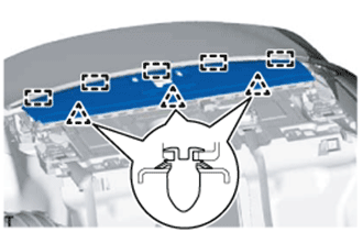
REMOVE PACKAGE TRAY TRIM PANEL ASSEMBLY
-
Using a moulding remover, detach the 4 claws and remove the rear seat shoulder belt hole cover.
Tech Tips
Use the same procedure to remove the rear seat shoulder belt hole cover on the other side.
-
Using a moulding remover, detach the 4 claws and remove the belt guide of the rear seat inner with center belt assembly LH.
-
w/o Rear Sunshade:
-
Detach the 4 claws and remove the center stop light cover.
-
Disconnect the connector.
-
Detach the 4 clips, and then slide the package tray trim panel assembly towards the front of the vehicle to detach the 5 guides.
-
Pass the 3 rear seat belt floor anchors through the package tray trim panel assembly and remove the package tray trim panel assembly.
-
-
w/ Rear Sunshade:
-
Detach the 4 clips, and then slide the package tray trim panel assembly towards the front of the vehicle to detach it from the rear window shade assembly.
-
Pass the 3 rear seat belt floor anchors through the package tray trim panel assembly and remove the package tray trim panel assembly.
-
-
-
REMOVE CENTER STOP LIGHT COVER (w/ Rear Sunshade)
-
Detach the 4 claws and remove the center stop light cover.
-
Disconnect the connector.
-
-
REMOVE NO. 2 PACKAGE TRAY TRIM PANEL ASSEMBLY (w/ Rear Sunshade)
-
Detach the 3 clips and 5 guides and remove the No. 2 package tray trim panel assembly.
-
-
REMOVE NO. 2 ROOM PARTITION PAD
-
Using a clip remover, remove the 2 clips and No. 2 room partition pad.
-
-
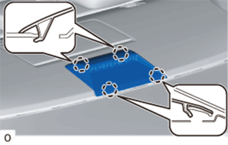
REMOVE NO. 1 ROOM PARTITION PAD
-
Using a clip remover, remove the 5 clips and No. 1 room partition pad.
-
-
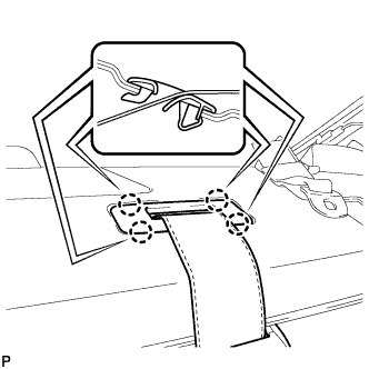
REMOVE LUGGAGE COMPARTMENT TRIM COVER RH
-
Remove the luggage compartment trim cover RH.
-
-
REMOVE SIDE TRIM BOX
-
Remove the side trim box.
-
-
REMOVE LUGGAGE COMPARTMENT SIDE TRAY (w/ Spare Tire)
-
Remove the luggage compartment side tray.
-
-
REMOVE LUGGAGE COMPARTMENT TRIM BOX (w/o Spare Tire)
-
Remove the luggage compartment trim box.
-
-
REMOVE SPARE WHEEL COVER TRAY (w/o Spare Tire)
-
Remove the spare wheel cover tray.
-
-
REMOVE ROPE HOOK ASSEMBLY
Tech Tips
Use the same procedure for all rope hooks.
-
Detach the 2 claws and open the cover.
-
Remove the bolt and rope hook assembly.
-
-
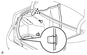
REMOVE REAR LUGGAGE COMPARTMENT TRAY BRACKET LH
-
Remove the clip.
-
Detach the claw and remove the rear luggage compartment tray bracket LH.
-
-
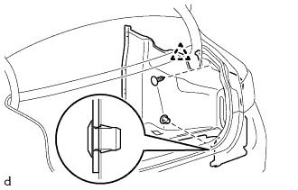
REMOVE REAR LUGGAGE COMPARTMENT TRAY BRACKET RH
Tech Tips
Use the same procedure described for the LH side.
-
REMOVE NO. 1 LUGGAGE COMPARTMENT TRIM HOOK
-
Detach the 2 claws and remove the No. 1 luggage compartment trim hook.
-
-
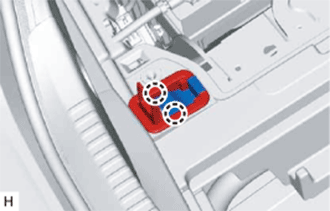
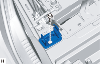
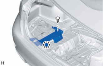
REMOVE NO. 1 LUGGAGE COMPARTMENT LIGHT ASSEMBLY
-
Text in Illustration *1 Protective Tape Using a screwdriver wrapped with protective tape, detach the 2 claws and remove the No. 1 luggage compartment light assembly.
-
Disconnect the connector.
-
-
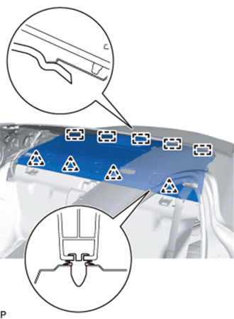
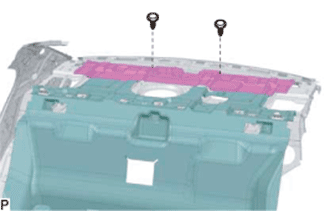
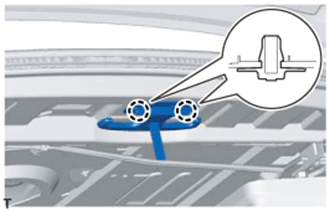
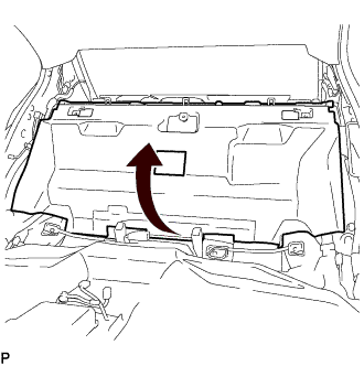
REMOVE REAR LUGGAGE COMPARTMENT TRIM COVER
-
Remove the 3 No. 2 luggage compartment trim hooks as shown in the illustration.
-

Remove the 5 clips.
-
Detach the 3 guides and remove the rear luggage compartment trim cover.
-
-
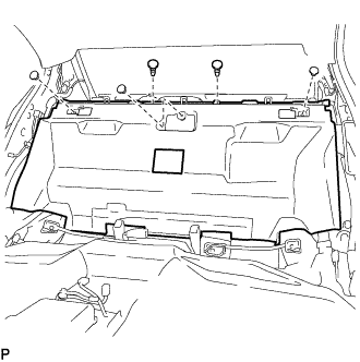
REMOVE REAR FLOOR FINISH PLATE
-

Remove the 3 clips.
-
Detach the 6 clips and remove the rear floor finish plate.
-
-
REMOVE FRONT LUGGAGE COMPARTMENT TRIM COVER
-
Remove the 3 clips, 2 nuts and front luggage compartment trim cover.
-
-
REMOVE ROPE HOOK
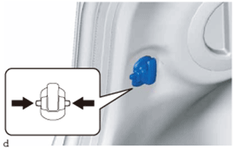
Tech Tips
Use the same procedure for both rope hooks.
-
Pinch the rope hook as indicated by the arrows in the illustration to remove the rope hook.
-
-
REMOVE INNER LUGGAGE COMPARTMENT TRIM COVER LH
-
Using a clip remover, remove the clip.
-
Detach the 2 claws and remove the clip.
-
Detach the clip and remove the luggage compartment trim inner cover LH.
-
-
REMOVE INNER LUGGAGE COMPARTMENT TRIM COVER RH
-
Using a clip remover, remove the clip.
-
Detach the 2 claws and remove the clip.
-
Detach the clip and remove the luggage compartment trim inner cover RH.
-
-
REMOVE NO. 6 HYBRID BATTERY INTAKE DUCT
Tech Tips
If the message "Cooling performance of the hybrid battery is low Consult a dealer" is displayed on the multi-information display in the combination meter assembly, inspect the No. 6 hybrid battery intake duct after removing it Click here.
-
Roll up the No. 1 room partition pad.
-
Remove the 2 clips.
-
Disconnect the No. 6 hybrid battery intake duct from the No. 3 hybrid battery intake duct and remove it.
-
-
REMOVE NO. 1 HYBRID BATTERY INTAKE DUCT
Tech Tips
If the message "Cooling performance of the hybrid battery is low Consult a dealer" is displayed on the multi-information display in the combination meter assembly, inspect the No. 1 hybrid battery intake duct after removing it Click here.
-
Remove the 2 clips.
-
Disconnect the No. 1 hybrid battery intake duct from the No. 3 hybrid battery intake duct and remove it.
-
-
REMOVE NO. 3 HYBRID BATTERY INTAKE DUCT
-
Remove the 3 clips.
-
Disconnect the No. 3 hybrid battery intake duct from the battery cooling blower assembly and remove it.
-
-
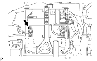
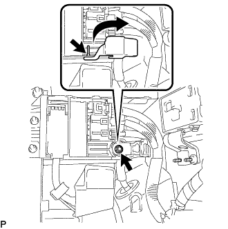
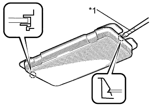
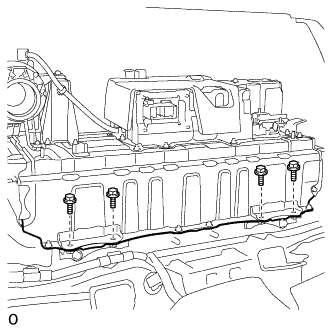
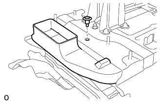
REMOVE NO. 4 HYBRID VEHICLE BATTERY SHIELD SUB-ASSEMBLY
CAUTION:
Perform work using insulated gloves and insulated tools.
-
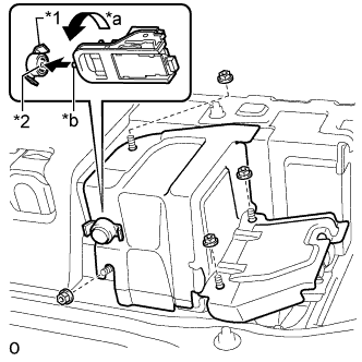
Text in Illustration *1 Battery Cover Lock Striker *2 Button *a Counterclockwise *b Protrusion Using the service plug grip, insert the protrusion part of the service plug grip, turn the button of the battery cover lock striker counterclockwise, and release the lock.
-
Remove the 4 nuts and No. 4 hybrid vehicle battery shield sub-assembly.
-
-
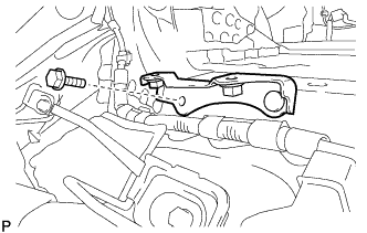
DISCONNECT NO. 4 FLOOR WIRE
CAUTION:
Perform work using insulated gloves and insulated tools.
-
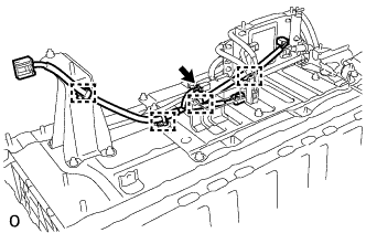
Remove the battery shield contact.
-
Detach the wire harness clamp.
-
Remove the 2 nuts and disconnect the 2 wires of the No. 4 floor wire.
Note
Insulate the terminals of the disconnected high voltage wire with insulating tape.
-
-
REMOVE NO. 1 HYBRID BATTERY CARRIER BRACKET
CAUTION:
Be sure to wear insulated gloves.
-
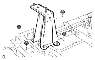
Remove the 2 nuts.
-
Remove the 4 bolts and No. 1 hybrid battery carrier bracket.
-
-
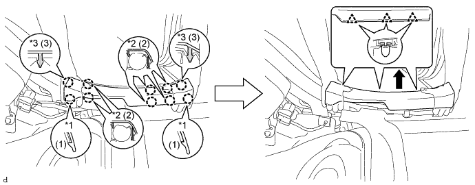
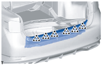
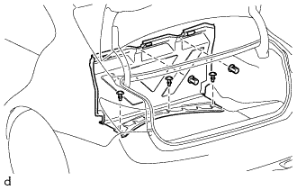
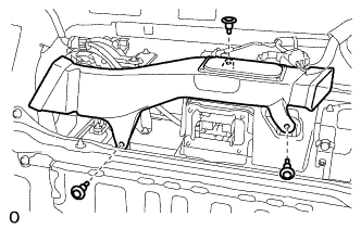
REMOVE HV BATTERY
CAUTION:
Be sure to wear insulated gloves.
-
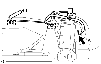
Disconnect the 2 connectors and detach the wire harness clamp from the upper part of the battery cooling blower assembly.
-
Disconnect the connector from the brake control power supply assembly.
-
Remove the 4 bolts.
-
Install the luggage compartment floor mat upside down.
-
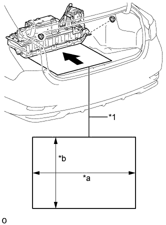
Text in Illustration *1 Cardboard *a 920 mm (3.01 ft.) *b 540 mm (1.77 ft.) Prepare 2 pieces of cardboard that are at least 540 mm (1.77 ft.) long and 920 mm (3.01 ft.) wide.
-
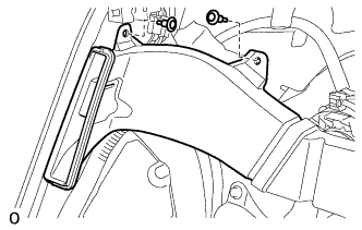
Remove the 2 nuts and lift the HV battery, alternating between the left and right sides. Then, place the 2 pieces of cardboard on top of one another and slide them under the HV battery.
-
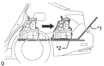
Text in Illustration *1 Top piece of cardboard *2 Bottom piece of cardboard Pull out the HV battery and top piece of cardboard together from the rear of the vehicle, sliding them over the bottom piece of cardboard.
Note
-
When pulling out the HV battery, 2 people are needed. One should work from the luggage compartment side and the other from the cabin side.
-
When pulling out the HV battery, do not allow the wire harnesses and the HV battery case to interfere with the vehicle body.
-
Make sure that the hybrid battery cover sheet attached to the underside of the HV battery does not come off.
-
-
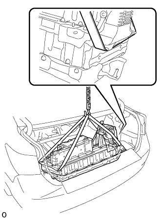
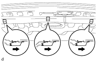
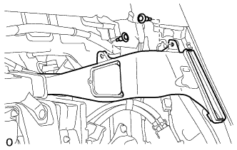
Using a rope or equivalent, remove the HV battery from the vehicle.
Note
-
Use cardboard or other similar material to protect the HV battery and vehicle body from damage.
-
Pass the rope or equivalent as shown in the illustration in order to prevent deformation.
-
-
-
REMOVE NO. 1 UPPER HYBRID VEHICLE BATTERY CARRIER BRACKET
-
Remove the bolt and No. 1 upper hybrid vehicle battery carrier bracket.
-
-
REMOVE NO. 2 UPPER HYBRID VEHICLE BATTERY CARRIER BRACKET
-
Remove the bolt and No. 2 upper hybrid vehicle battery carrier bracket.
-
-
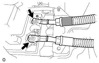
REMOVE NO. 2 BATTERY PACK WIRE
CAUTION:
Be sure to wear insulated gloves.
-
Text in Illustration *A w/ Voltage Inverter w/ Voltage Inverter:
Disconnect the connector.
-
Detach the 3 wire harness clamps and remove the No. 2 battery pack wire.
-
-
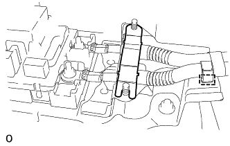
REMOVE VOLTAGE INVERTER ASSEMBLY (w/ Voltage Inverter)
-
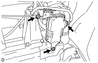
for 2AR-FSE:
-
Disconnect the connector and detach the clamp.
-
Remove the 2 nuts and voltage inverter assembly.
-
-
for 2GR-FXE:
-
Disconnect the connector.
-
Remove the bolt and disconnect the wire harness.
-
Remove the 2 nuts and voltage inverter assembly.
-
-
-
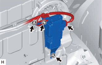
REMOVE BATTERY COOLING BLOWER ASSEMBLY
CAUTION:
Perform work using insulated gloves and insulated tools.
-
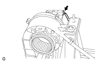
Disconnect the connector and detach the wire harness clamp.
-
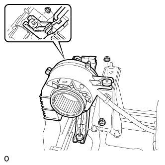
Remove the 3 nuts and battery cooling blower assembly.
Note
-
Hold the wire harness and fan, and do not remove them.
-
Make sure that foreign matter does not enter the battery cooling blower assembly.
-
-
-
REMOVE NO. 2 HYBRID BATTERY INTAKE DUCT
CAUTION:
Be sure to wear insulated gloves.
-
Using a clip remover, remove the clip.
-
Remove the No. 2 hybrid battery intake duct.
-
-
REMOVE NO. 1 HYBRID BATTERY SILENCER
CAUTION:
Be sure to wear insulated gloves.
-
Remove the No. 1 hybrid battery silencer.
-
-
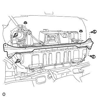
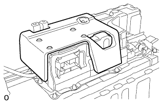
REMOVE UPPER HYBRID BATTERY COVER SUB-ASSEMBLY
CAUTION:
Perform work using insulated gloves and insulated tools.
-
Remove the 8 nuts and upper hybrid battery cover sub-assembly.
-
-
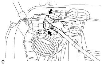
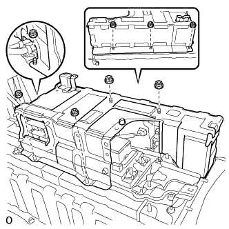
REMOVE HYBRID BATTERY JUNCTION BLOCK ASSEMBLY
CAUTION:
Perform work using insulated gloves and insulated tools.
-
Disconnect the 4 connectors.
Note
Insulate the disconnected high voltage connectors with insulating tape.
Tech Tips
High voltage wiring connectors are orange.
-
Remove the 3 nuts and hybrid battery junction block assembly.
Note
If the hybrid battery junction block assembly has been dropped, replace it with a new one.
-
-
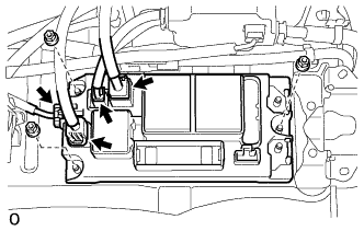
REMOVE BATTERY SMART UNIT
CAUTION:
Perform work using insulated gloves and insulated tools.
-
Disconnect the 3 connectors.
Note
Insulate the disconnected high voltage connectors with insulating tape.
Tech Tips
High voltage wiring connectors are orange.
-
Remove the 2 nuts.
-
Detach the guide and remove the battery smart unit.
-
-
REMOVE NO. 2 HYBRID BATTERY PACK WIRE
CAUTION:
Be sure to wear insulated gloves.
-
Disconnect the connector.
-
Detach the 4 wire harness clamps and remove the No. 2 hybrid battery pack wire.
-
-
REMOVE NO. 2 HYBRID BATTERY CARRIER BRACKET SUB-ASSEMBLY
CAUTION:
Perform work using insulated gloves and insulated tools.
-
Remove the 4 nuts and No. 2 hybrid battery carrier bracket sub-assembly.
-